HAL Id: tel-02274361
https://pastel.archives-ouvertes.fr/tel-02274361
Submitted on 29 Aug 2019
HAL is a multi-disciplinary open access
archive for the deposit and dissemination of sci-entific research documents, whether they are pub-lished or not. The documents may come from teaching and research institutions in France or
L’archive ouverte pluridisciplinaire HAL, est destinée au dépôt et à la diffusion de documents scientifiques de niveau recherche, publiés ou non, émanant des établissements d’enseignement et de recherche français ou étrangers, des laboratoires
Wireless sensor networks for indoor mapping and
accurate localization for low speed navigation in smart
cities
Dinh-Van Nguyen
To cite this version:
Dinh-Van Nguyen. Wireless sensor networks for indoor mapping and accurate localization for low speed navigation in smart cities. Robotics [cs.RO]. Université Paris sciences et lettres, 2018. English. �NNT : 2018PSLEM029�. �tel-02274361�
Préparée à MINES ParisTech
Wireless Sensors Networks for Indoor Mapping and
Accurate Localization for Low Speed Navigation in
Smart Cities
Réseaux de capteurs sans-fil pour la cartographie à
l’intérieur et la localisation précise servant la navigation
à basse vitesse dans les villes intelligentes
Soutenue par
Dinh-Van NGUYEN
Le 05 Dec 2018
Ecole doctorale n° 432
Sciences des Métiers de
l’Ingénieur
Spécialité
Informatique temps réel,
robotique et automatique
Composition du jury : Paul, MUHLETHALER Directeur de recherche, INRIA
Président
Vincent, FREMONT
Professeur, Ecole Central Nantes
Rapporteur
Samia, AINOUZ
Maître de conférences, INSA de Rouen
Rapporteur
Trung-kien, DAO
Lecturer-Researcher, MICA Institute
Co-Directeur de these Eric, CASTELLI Chargé de recherche, CNRS Co-Directeur de thèse Fawzi, NASHASHIBI
Directeur de recherche, INRIA
A
BSTRACT
With the increasing demand for urban space, more and more multistory carparks are needed. Although these carparks help to utilize urban space more efficient, they also introduce a new problem. Reports suggest approximately 70 million hours of parking slot searching each year, equivalently 700 million euros loss for France alone. In addition, carparks uses are exceeding their original purposes. Demanding features such as electric charger, online booking of parking spaces, dynamic guidance or mobile payment etc. turn a carpark into a competitive smart environment. One solution to this problem is to develop an autonomous navigation system for intelligent vehicles in the carpark situation. The thesis will identify one of these sub-tasks namely localization in GPS-denied environments. This thesis will present a novel method to solve the indicated problem while keeping the system follows four criteria: availability, scalability, universality and accuracy. There are two main steps: (1) a solution to replicate the GPS behaviour for the GPS-denied environment, and (2) a framework that allows the fusion of GPS-like systems with other localization methods to achieve a high localization accuracy. First, a Wi-Fi Fingerprinting localization system is employed. An approach using an ensemble neural network on a hybrid Wi-Fi fingerprinting database is proposed in this thesis. Experiments in a year-long duration show that this system is capable of localizing vehicles with 2.25m of mean error in the global coordinate frame (WGS84). Second, a complete localization solution must be a fusion of multiple techniques. This allows global as well as local levels of localization to function together. At the same time, having redundancy in the system boosts accuracy and reliability. In this thesis, a flexible fusion framework for multiple localization sensors is proposed. This fusion framework will not only deal with the GPS-denied environment but could be potentially used in the GPS-aided environment and provide a smooth transition between the two areas. To accomplish this demanding task, a Gaussian Mixture Model Particle Filter is developed. While the motion model of this particle filter incorporates data from the IMU (Inertial Measurement Unit) or laser-SLAM, the correction model is a Gaussian mixture model of multiple observations obtained from the Wi-Fi fingerprinting localization system. With two intelligent vehicles (a Cybercar and a Citroen C1 car), 64 experiments were carried out to validate the framework. A mean localization error of 0.5m is achieved in a global coordinate frame. Compare to other solutions with 0.2m of mean localization error in local coordinate frames; this proposed solution has advantages in terms of scalability, availability and universality as well.
MINES ParisTech
Unité Mathématiques et Systèmes
A
CKNOWLEDGEMENTS
I would like to thank my family, my wife Linh, my parents, my sister and our little cat for all the support. No word can describe how much they mean to me.
To my supervisors, thank you! You all have been so patient and thoughtful with me. You gave me this extraordinary opportunity at the beginning and accomplishing this thesis would not be possible without your advices.
To my colleagues, Raoul, Anne, Jean-Marc, and the PhD gang, thank you! You all have been fantastic. I could not ask for a better team.
C
ONTENTS
1. INTRODUCTION ... 1 1.1CONTEXT ... 2 1.2SCOPE ... 4 1.3MAIN CONTRIBUTIONS ... 6 1.4THESIS OVERVIEW ... 72. INTELLIGENT VEHICLES LOCALIZATION ... 10
2.1OVERVIEW OF INTELLIGENT VEHICLES LOCALIZATION ... 14
2.2GPS-BASED LOCALIZATION ... 15
2.3LASER-BASED LOCALIZATION ... 20
2.3.1 Filter-based Laser SLAM ... 21
2.3.2 Optimization-based Laser SLAM ... 23
2.4VISION-BASED LOCALIZATION ... 24
2.5DEAD-RECKONING ... 25
2.6INTELLIGENT VEHICLES LOCALIZATION IN GPS-DENIED ENVIRONMENTS ... 27
2.6.1 Absolute Localization ... 27
2.6.2 Relative Localization ... 31
2.7DISCUSSION ... 32
3. WIRELESS SENSOR NETWORKS LOCALIZATION ... 36
3.1INTRODUCTION ... 37
3.2LOCALIZATION STRATEGIES OVERVIEW ... 38
3.3RANGE-BASED APPROACH ... 38
3.3.1 Time of Arrival ... 38
3.3.2 Angle of Arrival ... 40
3.3.3 Received Signal Strength Indicator ... 42
3.4RANGE-FREE APPROACH ... 43
3.4.1 Distance Vector Hop ... 43
3.4.2 Approximate Point-in-Triangulation Test ... 45
3.4.3 Fingerprinting Localization ... 45
3.4.4 Centroid Localization ... 47
3.5DISCUSSION ... 47
MINES ParisTech
Unité Mathématiques et Systèmes
4.2RELATED WORKS ... 56
4.3 ENSEMBLE APPROACH FOR WI-FI FINGERPRINTING LOCALIZATION OF INTELLIGENT VEHICLES ... 61
4.3.1 Hybrid Database Offline Phase ... 62
4.3.2 Wi-Fi Ensemble Neural Network ... 65
4.4EXPERIMENTS AND RESULTS ... 70
4.4.1 Survey of the Wi-Fi Characteristics in the Experiment Area ... 72
4.4.2 Wi-Fi localization Experiments ... 75
4.5DISCUSSION ... 78
5. FUSION STRATEGY FOR LOCALIZATION ENHANCEMENT ... 81
5.1INTRODUCTION ... 83
5.2THE PARTICLE FILTER ... 86
5.2.1 Initialization Step ... 87
5.2.2 Prediction Step ... 87
5.2.3 Correction Step ... 88
5.2.4 Selection & Resampling Step ... 89
5.3GAUSSIAN MIXTURE MODEL PARTICLE FILTER ... 90
5.3.1 Initialization Step ... 91
5.3.2 Correction Step ... 92
5.4FUSION OF WI-FI FINGERPRINTING AND IMU ... 95
5.4.1 Inputs Synchronization ... 96
5.4.2 Particles Propagation ... 97
5.4.3 Motion model... 97
5.4.4 Selection & Resampling ... 98
5.5FUSION OF WI-FI FINGERPRINTING,IMU AND LASER-SLAM ... 99
5.5.1 Evidential SLAM ... 100
5.5.2 PML-SLAM... 102
5.5.3 SLAM in Global Coordinate Frame ... 104
5.5.4 SLAM as Odometry Measurements ... 106
5.6EXPERIMENTS AND RESULTS ... 108
5.6.1 Wi-Fi Fingerprinting Localization and IMU Fusion ... 108
5.6.2 Wi-Fi Fingerprinting Localization, IMU and Laser-SLAM fusion ... 118
6. CONCLUSION ... 126 6.1THESIS MOTIVATION ... 127 6.2THESIS CONTRIBUTIONS ... 128 6.3FUTURE WORK ... 130 6.4CONCLUSION ... 131 7. REFERENCES ... 133 8. APPENDIX 1: RÉSUMÉ ... 149 9. APPENDIX 2: ABSTRACT ... 162
MINES ParisTech
Unité Mathématiques et Systèmes
L
IST OF
T
ABLES
Table 1 Service performance standard for SPS (Department Of Defense 2008; “GPS
Performances - Navipedia” 2018) ... 16
Table 2 Service performance standard for PPS (“GPS Performances - Navipedia” 2018; GPS Directorate 2007)... 16
Table 3 Comparison between global positioning systems (Hofmann-Wellenhof, Lichtenegger, and Wasle 2018) ... 20
Table 4 Comparison of different WSNs localization techniques ... 54
Table 5 Positioning Error using BLE and Wi-Fi fingerprinting (Wilfinger and Thesis 2015) 58 Table 6 Wi-Fi fingerprinting localization using 13 fingerprints ... 73
Table 7 Correlation between the average Wi-Fi signal strength and the localization error ... 74
Table 8 Top 3 highest confidence fingerprints as the classification result ... 77
Table 9 Wi-Fi ensemble fingerprinting localization error ... 77
Table 10 Comparison of Algorithms for Nonlinear Filtering (Daum 2005) ... 85
L
IST OF
F
IGURES
Figure 1.1 Parkmatic – Automated Parking System (“Parkmatic - Multi Parking” 2018) ... 3
Figure 1.2 OneSITU – Parking Management System (“Parking Solutions - Solutions - OneSITU” 2018) ... 4
Figure 1.3 World Geodetic Coordinate System WGS84 (Malys et al. 2015) ... 5
Figure 2.1 Fusion of localization systems ... 15
Figure 2.2 GPS principle ... 16
Figure 2.3 The Galileo satellites navigation system commercial service architecture (Fernández-Hernández et al. 2018) ... 18
Figure 2.4 The kinematic high precision positioning results of Galileo (Ignacio, Irma, and Guillermo 2015) ... 19
Figure 2.5 The GLONASS accuracy evolution (“GLONASS Performances - Navipedia” 2018) ... 19
Figure 2.6 Graphical representation of (a) Full SLAM problem; (b) Online SLAM problem (Bresson et al. 2017)... 20
Figure 2.7 Particle Filter based Evidential SLAM (Trehard et al. 2014) ... 22
Figure 2.8 GraphSLAM visualization of large scale forest mapping (Pierzchała, Giguère, and Astrup 2018) ... 23
Figure 2.9 GPS-aided SLAM for large scale uban mapping (Carlson, Thorpe, and Browning 2010)... 24
Figure 2.10 Edge-filtered map of the environment (Borges et al. 2010) ... 25
Figure 2.11 Camera image to edge image transformation (Borges et al. 2010) ... 25
Figure 2.12 Dead-reckoning and static map (Fouque et al. 2008) ... 27
Figure 2.13 Graphical representation of SLAM with a static map (Wahl et al. 2015) ... 28
Figure 2.14 2D map and LiDAR reading of the obstacle-free environment (Ibisch et al. 2013) ... 29
MINES ParisTech
Unité Mathématiques et Systèmes
Figure 2.16 Flow chart of 3D map-matching based on particle filter (Bojja et al. 2013) ... 31
Figure 2.17 Fisheye-based parking lot searching (Houben et al. 2013) ... 32
Figure 2.18 Two levels of localization system ... 33
Figure 3.1 Two-way scheme of TOA ... 39
Figure 3.2 Angle of Arrival (AOA) localization method (Yin et al. 2016) ... 41
Figure 3.3 Angel of Arrival confidence zone ... 41
Figure 3.4 Array Track localization error ... 42
Figure 3.5 Signal propagation through obstacles (Dao et al. 2014) ... 43
Figure 3.6 DV-Hop distance ... 44
Figure 3.7 Approximate point-in-triangulation test (F. Liu and Tan 2012) ... 45
Figure 3.8 Fingerprinting localization concept ... 46
Figure 3.9 Centroid algorithm concept (Hongyang Chen et al. 2008) ... 47
Figure 4.1 Fingerprints illustration... 54
Figure 4.2 iParking system architecture (J. Liu et al. 2012) ... 56
Figure 4.3 Thondorf carpark (Wilfinger and Thesis 2015) ... 57
Figure 4.4 Time series for a test run (Wilfinger and Thesis 2015) ... 57
Figure 4.5 Sensors setup and testing environment (Gikas et al. 2016) ... 59
Figure 4.6 The Universidad Carlos II de Madrid campus (Hernandez et al. 2017) ... 59
Figure 4.7 General architecture of the system (Hernandez et al. 2017) ... 60
Figure 4.8 Cumulative Distribution of Error (Hernandez et al. 2017) ... 60
Figure 4.9 Wi-Fi localization in urban area (Ang 2018) ... 61
Figure 4.10 Cumulative distribution of error in urban area (Ang 2018) ... 61
Figure 4.11 Online scan range for different speeds ... 62
Figure 4.12 Distance between two adjacent fingerprints ... 64
Figure 4.13 Ensemble of estimators motivation (Dietterich 2000) ... 67
Figure 4.15 Boostrap hybrid database ... 69
Figure 4.16 Testing area in INRIA Rocquencourt campus ... 71
Figure 4.17 Blue Cybercar and Red Citroen C1 ... 71
Figure 4.18 The Wi-Fi heat map of the testing area ... 72
Figure 4.19 13 Reference points in the environment ... 73
Figure 4.20Number of detected access points for each reference point ... 73
Figure 4.21 Distribution of localization error for each fingerprint ... 74
Figure 4.22 Cumulative distribution of the localization error for fingerprints 1-9 ... 75
Figure 4.23 The experiment area with 25 fingerprints ... 75
Figure 4.24 Localization result for 1 run ... 77
Figure 5.1 Particle Filter Flowchart ... 88
Figure 5.2 Particle filter and Wi-Fi fingerprinting flowchart ... 91
Figure 5.3 Gaussian Mixture Model Estimation ... 93
Figure 5.4 Single Gaussian Model Estimation ... 93
Figure 5.5 Gaussian Mixture Model in Practice 1 ... 94
Figure 5.6 Gaussian Mixture Model in Practice 2 ... 95
Figure 5.7 Gaussian Mixture Model Particle Filter with IMU and Wi-Fi fingerprinting ... 96
Figure 5.8 Input Synchronization Timestamp ... 96
Figure 5.9 General architecture for Evidential SLAM (Trehard et al. 2014) ... 101
Figure 5.10 Evidential SLAM test drive in KITTI database (Trehard et al. 2014) ... 102
Figure 5.11 General flowchart of the PML-SLAM algorithm (Alsayed et al. 2015) ... 103
Figure 5.12 Test drive on KITTI database with PML-SLAM (Alsayed et al. 2015) ... 103
Figure 5.13 Deviation of distance and heading for PML SLAM (Alsayed et al. 2015) ... 104
Figure 5.14 Fusion of laser-SLAM, Wi-Fi fingerprinting and IMU ... 106
MINES ParisTech
Unité Mathématiques et Systèmes
Figure 5.16 True position during the initialization step: within fingerprint area (red) and outside
fingerprint area (blue)... 109
Figure 5.17 Initial position within the defined fingerprint area case ... 111
Figure 5.18 Experiment test run ... 111
Figure 5.19 Localization error with corresponding ground truth quality ... 112
Figure 5.20 Travel path with RTK GPS quality ... 112
Figure 5.21 Initial position outside the defined fingerprint area case ... 113
Figure 5.22 Experiment test run ... 114
Figure 5.23 Initial position within a fingerprint area ... 115
Figure 5.24 Initial position outside a fingerprint area ... 115
Figure 5.25 Localization error histogram of all experiments ... 116
Figure 5.26 Cumulative sum of errors for all experiments ... 116
Figure 5.27 Localization error histogram (good initial position) ... 117
Figure 5.28 Cumulative sum of localization error (good initial position) ... 117
Figure 5.29 laser-SLAM in Global Coordinate ... 118
Figure 5.30 Fusion System (Wi-Fi and laser-SLAM) in the Global Coordinate Frame ... 119
Figure 5.31 Localization error of fusion solution ... 120
Figure 5.32 Experiment test run ... 120
Figure 5.33 PML-SLAM online map ... 121
L
IST OF
A
BBREVIATIONS AND
A
CRONYMS
Abbreviation Full Name
AOA Angle of Arrival
APIT Approximate Point In Triangulation Test
CV Coefficient of Variation
DGPS Differential Global Positioning System
DV-hop Distance Vector Hop
EKF Extended Kalman Filter
EPS Effective Particle Size
FP Fingerprint
GMM Gaussian Mixture Model
GNSS Global Navigation Satellite System
GPS Global Positioning Systems
ICP Iterative Closest Points
IMU Inertial Measurement Unit
IoT Internet of Things
ITS Intelligent Transportation Systems
KNN K-Nearest Neighbours
OOI Object of Interest
PML Probabilistic Maximum Likelihood
PPS Precise Positioning Service
RIOs Road Infrastructure Objects
RMSE Root Mean Square Error
MINES ParisTech
Unité Mathématiques et Systèmes
RTK Real-time Kinematic
SLAM Simultaneous Localization and Mapping
SPS Standard Positioning Service
SVM Support Vector Machine
TDOA Time Difference of Arrival
TOA Time of Arrival
V2I Vehicle to Infrastructure
WEFLS Wi-Fi Ensemble Fingerprinting Localization System
WLAN Wireless Local Area Network
1. I
NTRODUCTION
Résumé
Le chapitre présente la motivation, la portée et le but de la thèse. Cette thèse débute avec la collaboration de deux unités de recherche, l’équipe RITS, l’INRIA France et l’institut MICA, et est financée par le programme de bourses d’études 911 du gouvernement vietnamien. comme autoroute, rues urbaines, etc. L’environnement sans GPS, qui est également un scénario important pour les applications de véhicules intelligents, n’a pas encore été totalement traité. Un environnement notable pour un tel scénario est un parking couvert. Cette thèse a pour objectif de trouver une nouvelle solution au problème de localisation dans un environnement sans GPS. Les solutions existantes pour ce scénario sont coûteuses à déployer ou ne permettent pas de résoudre complètement le problème. Par conséquent, la solution doit être une méthode de localisation globale qui permette une transition transparente entre la localisation d’environnement assistée par GPS et celle qui est refusée par le GPS et satisfasse à quatre critères: disponibilité, évolutivité, universalité et précision. Deux contributions principales sont proposées: un système de localisation d'empreintes digitales d'ensemble Wi-Fi capable de reproduire le comportement du GPS pour l'environnement sans GPS et un cadre de fusion de filtres à particules mélangées gaussien permettant la fusion de techniques de localisation multiples.
Chapter 1: Introduction ---
Nguyen Dinh Van - January 2019 2
1.1 Context
The thesis is conducted in collaboration of two research units: RITS team, INRIA France and MICA Institute, Vietnam and funded by Vietnamese government scholarship program 911. RITS (Robotics for Intelligent Transportation Systems) team is a multidisciplinary project team at INRIA, working on Robotics for Intelligent Transportation Systems. The team focuses on enabling advanced intelligent robotics systems for autonomous and sustainable mobility. One notable application is Intelligent Vehicles (IVs) which can navigate autonomously in different environments.
MICA (Multimedia, Information Communication and Application) International Research Institute is established in Vietnam by CNRS, Grenoble INP and Hanoi University of Science and Technology. One of its research interests is indoor localization in smart environments using wireless sensors networks. The main objective of this research is to enable indoor navigation for targets such as humans or robots.
With the increasing demand for urban space, more and more multistory carparks are needed. Although these carparks help to utilize urban space more efficient, they also introduce a new problem. Reports in (Belloche 2015; Gantelet and Lefauconnier 2006) suggest the average searching time for a free slot in a carpark in Paris or Lyon is 20 minutes and can be as high as 40 minutes for some districts. This leads to approximately 70 million hours of searching each year, equivalently 700 million euros loss for France alone. In addition, carparks uses are exceeding their original purposes. Demanding features such as electric charger, online booking of parking spaces, dynamic guidance or mobile payment etc. turn a carpark into a competitive smart environment. Furthermore, 20 most populous cities in France must engage an open data approach from October 1st, 2018 in accordance with the law for a digital Republic (“Loi Du 7
Octobre 2016 Pour Une République Numérique” 2016). This introduces a great chance to invent a new way to calculate traffic flow, develop intelligent services such as intelligent car parks (“Parking at the Service of Connected Urban Mobility and a Sustainable City - The Urban Mobility Blog” 2018).
Several solutions are developed such as automated carpark system (Skyline Inc. 2018; “Parkmatic - Multi Parking” 2018); smart car park guidance and management (“Parking Solutions - Solutions - OneSITU” 2018). Automated carpark system (Figure 1.1) is a complex, costly mechanical system that automatically collects vehicles and put them in specific places.
Chapter 1: Introduction ---
This solution requires a complete rebuild of a carpark. Although, a smart car park guidance and management system does not require such a high investment, it asks for various sensors and computing systems to guide users to a free parking lot from software level (Figure 1.2). These systems are either too costly or do not entirely eliminate time wasting issue. This is the motivation for intelligent vehicles to push toward fully autonomous navigation in an indoor situation such as a carpark to completely remove the time-wasting issue and enhance effectiveness and safety of car parking. With the centre role of car park in the transport chain, solving such problem would definitely benefit the traffic flow of the whole system. This solution will not only address the time-wasting issue but also enhance the parking space efficiency. According to report from the Audi’s Urban Futures Initiative program, the autonomous vehicles solution could save up to 62% of parking space by 2030 (Nourinejad, Bahrami, and Roorda 2018). This is equivalent to 100 million Dollars for a single district of the testing area in the program.
The dream of having an intelligent vehicle navigating autonomously in different environments, has been realized step by step during the last ten years. One of those steps is the challenging task of locating a vehicle position in different circumstances, conditions and environments. The lack of Global Positioning System (GPS) appears to be a significant concern for any localization system. While outdoor, GPS-aided localization for intelligent vehicles has been widely studied in recent years, indoor, GPS-denied localization is yet to be fully addressed.
Figure 1.1 Parkmatic – Automated Parking System (“Parkmatic - Multi Parking” 2018) From both theoretical and practical perspectives, the problem of navigation for intelligent vehicles in GPS-denied environment deserves a complete solution. This thesis will focus on solving a crucial part of it namely localization. The scope and objectives of the thesis will be presented in the following section.
Chapter 1: Introduction ---
Nguyen Dinh Van - January 2019 4
Figure 1.2 OneSITU – Parking Management System (“Parking Solutions - Solutions - OneSITU” 2018)
1.2 Scope
Autonomous navigation for an intelligent vehicle is a considerable task consisting of multiples sub-tasks. Rather than trying to find a complete solution at once, it is essential to identify each of these sub-tasks and deal with them separately. The thesis will identify one of these sub-tasks as follows.
In this thesis, the targeted environments are the one without GPS signal such as: indoor carpark. The targeted environment can also be extended to places with poor GPS signal and low movement speed such as industrial factory, university campus or outdoor carpark. Throughout this thesis, the term GPS-denied environment will be defined as an environment with poor or no GPS signal and GPS-aided environment refers to the one with good reception of GPS signal. At the same time, by targeting environment such as carpark, university campus, the average movement speed of vehicles is expected to be around 3m/s (Belloche 2015). This is due to the nature of these environments conditions as well as speed regulation applied. In fact, in recent demonstrations of companies like Audi, BMW, etc. for autonomous carpark navigation systems, vehicles are operated at around 10km/h. Understanding the vehicle's dynamics in the localization problem will help to accurately identify advantages/ disadvantages of different positioning methods.
There are two levels of localization: global localization and local localization. In global localization, the vehicle will be localized within World Geodetic Coordinate System (“World Geodetic System (WGS84) - GIS Geography” 2018). This is the coordinate system used by global positioning systems such as GPS, GLONASS, and GALILEO etc. The coordinate system gives a global, absolute pose for different local coordinates to refer to. It is also useful in extracting semantic information of the surrounding environment. Figure 1.3 provides a general definition of the latest standard WGS84 for World Geodetic System. In this level of localization,
Chapter 1: Introduction ---
the main objectives are to offer semantic data as well as a global reference frame thus localization accuracy is not necessary to be in centimetres. On the other hand, local localization refers to a local coordinate localization where accuracy level is supposed to be high. This level of localization is responsible for accurate navigation and real-time obstacle avoidance. In intelligent vehicles navigation, both levels of localization are required to accomplish the task of navigation in different environment setups.
Figure 1.3 World Geodetic Coordinate System WGS84 (Malys et al. 2015)
With multiple sensors running on different local coordinates, it is critical to have a global frame to express those sensors outputs together. In the GPS-denied environment, the lack of GPS signal not only omits the essential global coordinate reference but also introduces a significant gap in the transition phase between GPS-aided and GPS-denied environments. This thesis aims to provide a global localization level method for GPS-denied environment. The proposed solution should be able to replicate GPS signal behaviour for the indoor environment.
Also, a fusion framework is proposed so that other local localization techniques can be fused into the global frame. This allows the system to achieve both local and global levels of localization. In addition, this framework should be generic that it could be potentially applied for both GPS-aided and GPS-denied environments thus allows seamless navigation transition between these two environments.
With respect to the primary target of carpark environment, the system must comply with the following requirements:
- Availability: The system should be easily deployable on existing infrastructure of a carpark with limited requirements of changes in structures, hardware or software.
Chapter 1: Introduction ---
Nguyen Dinh Van - January 2019 6
- Universality: there should be no specific hardware/ firmware changes other than off-shelf devices. This removes the need for dedicated sensors to be mounted in different carparks in order for the system to work.
- Accuracy: While ideally the system should be accurate in order of centimetres, in terms of global localization for carpark situation, it is not necessary to be so. Methods such as Laser-SLAM (Simultaneous Localization and Mapping) or vision based localization can deal well with local accuracy. Still, the system accuracy should be able to identify vehicle positioning within a parking plot. According to French standard “Norme NF P 91-100” (“Norme Francaise, Parcs de Stationnement a Usage Privatif” 1996), the minimum width for a parking spot is 1.80m. This should be the upper bound of the system accuracy. The final fusion localization system in this thesis is expected to be within 0.5m of mean localization error. Ideally, the localization error of a fully autonomous vehicle is under 0.2m (Ziegler et al. 2014).
1.3 Main Contributions
The thesis has two main contributions. First, a novel Wi-Fi Ensemble Fingerprinting Localization System (WEFLS) for GPS-denied environment to replace the need of GPS signal. Second, a framework for the fusion of multiple localization methods such as: GPS based, IMU based, WEFLS based, laser-SLAM based.
There are currently no de facto standards for GPS-denied environment positioning systems design as a global solution similar to the one used in the GPS-aided environment (e.g. GPS, GLONASS, etc.). Regarding intelligent vehicle navigation in the carpark, several solutions are proposed including: laser-SLAM with static map matching (Wahl et al. 2015), Embedded LIDAR sensors in the environment (Ibisch et al. 2013), 3D map matching using vision sensors (Bojja et al. 2013) or detection of parking lot using vision sensors (Houben et al. 2013) etc. While these studies may allow up to 10cm of localization precision, they also come with high cost or requirements such as: costly setup of sensors, complex environment map required, and no global coordinate transformation addressed. An in-depth review of these studies will be presented in chapter 2.
First, this thesis will present a novel method for GPS-denied environment localization using wireless sensors networks, more specifically a Wi-Fi fingerprinting localization system. The method makes use of existing Wi-Fi infrastructure (Wi-Fi Access Points – APs, Wi-Fi receiver) to determine the target position based on an offline mapping phase. The main argument of this
Chapter 1: Introduction ---
method is that the combination of Wi-Fi signal strengths from multiple static APs in the environment for one position is unique. By learning these unique features for several key positions in the environment, one can estimate its location just by scanning Wi-Fi signals strengths.
Although Wi-Fi fingerprinting localization system is already a popular approach for indoor localization, so far it only targets pedestrian walking speed. The advantages of this method are its availability, scalability and universal characteristics where off the shelf hardware like Wi-Fi receivers and Wi-Fi access points are used without any modification. These sensors are also expected to be widely available nowadays in urban area. One main concern of this method is the low sampling frequency of Wi-Fi scan. In general, the time to complete a scan of Wi-Fi signals in a particular environment is around 1 second (1Hz). At 1.0 to 1.6m/s of human walking speed (Harkema, Behrman, and Barbeau 2012), this sampling frequency is adequate to deliver real-time localization results. However, as the thesis aims to target intelligent vehicles in the carpark at 3m/s, the classic approach of the Wi-Fi fingerprinting method is insufficient. Thus, an original approach using ensemble neural network on Wi-Fi fingerprinting method is proposed in this thesis.
Secondly, a complete localization solution must be a fusion of multiple techniques. This allows global as well as local levels of localization to function together. At the same time, having redundancy in the system boosts accuracy and reliability. In this thesis, a flexible fusion framework for multiple localization sensors is proposed. This fusion framework will not only deal with the GPS-denied environment but could be potentially used in the GPS-aided environment and provide a smooth transition between the two areas.
1.4 Thesis Overview
Following this introduction, the thesis has 5 more chapters presented as follows:
- Chapter 2: A brief overview of intelligent vehicles localization, particularly, localization in the GPS-denied environment. The two categories of localization methods: absolute localization and relative localization are reviewed and discussed.
- Chapter 3: A summary of Wireless Sensors Networks and its strategies for localization. Two main strategies of this approach are range-based and range-free localization. This chapter will provide discussion to highlight the motivation of using WSNs in intelligent localization for GPS-denied environment.
Chapter 1: Introduction ---
Nguyen Dinh Van - January 2019 8
- Chapter 4: The core algorithm of the preferred WSNs localization strategy is presented. The Wi-Fi fingerprinting localization method is introduced with critical improvement to adapt to intelligent vehicle dynamics.
- Chapter 5: To enhance localization accuracy as well as frequency, a data fusion model is proposed using Gaussian Mixture Model and Particle Filter. This strategy is also capable of providing a smooth transition from the GPS-aided environment to GPS-denied environment. The model is then verified by fusing Wi-Fi Fingerprinting localization with IMU and PML-SLAM.
- Chapter 6: A conclusion of the thesis. It also highlights possible future work for this thesis and discusses multiple perspectives regarding the results obtained.
10
2. I
NTELLIGENT
V
EHICLES
L
OCALIZATION
Résumé
Dans ce chapitre, quelques techniques générales pour la localisation de véhicules intelligents sont examinées. En outre, une étude des solutions existantes pour la localisation de véhicules intelligents dans des environnements sans GPS est présentée.
En général, les techniques de localisation IV peuvent être divisées en deux catégories: la localisation globale et la localisation locale. Souvent, la catégorie de localisation globale est une méthode de localisation basée sur GNSS. Ces méthodes utilisent les signaux satellites pour déterminer les informations de position 3D du récepteur dans une référence globale (telle que WGS84). Le terme GPS fait référence au système de positionnement global qui est régi par les États-Unis d'Amérique. Il existe d'autres systèmes mondiaux de navigation par satellite (GNSS) tels que GLONASS (Russie), Galileo (Europe) et Beidou (Chine). Pour simplifier le problème, la thèse se concentrera sur les performances du GPS en tant que représentant d'autres GNSS. Le principe de calcul de la position du récepteur est basé sur la connaissance des positions des satellites, puis sur la déduction des «pseudo-distances» respectives entre ces satellites et le récepteur, comme illustré à la figure 2.2. Ici, le terme "pseudo-distance" se réfère à la distance calculée entre les satellites et le récepteur mobile. Étant donné que les satellites se déplacent constamment, cette distance n’est pas une valeur fixe. Pour calculer la position 3D d'un récepteur, il faut au moins quatre satellites. Vous trouverez un aperçu du système GPS dans (Hofmann-Wellenhof, Lichtenegger et Wasle 2018).
Il existe deux niveaux de services GPS, à savoir le service de positionnement standard (SPS) et le service de positionnement précis (PPS). Alors que SPS est accessible aux utilisateurs publics, les PPS de haute précision ne sont accessibles qu'aux utilisateurs autorisés (personnel militaire,
Chapter 2: Intelligent Vehicles Localization ---
agents de l'État). Le tableau 1 et le tableau 2 récapitulent les performances SPS et PPS. En général, SPS fournit une erreur de localisation maximale de 7,8 m dans 95% des cas, et le système PPS offre une meilleure précision avec une erreur de localisation maximale de 5,9 m dans 95% des heures. temps. En outre, la précision verticale devrait être inférieure à la précision horizontale dans toutes les mesures GPS. Dans le meilleur des cas, une solution DGPS de haute précision appelée GPS cinématique en temps réel (RTK GPS) peut offrir une précision de quelques centimètres. Cependant, le procédé nécessite des stations de base dédiées, des capteurs, des signaux GPS continus et un prix excessif pour le déploiement et la maintenance. Cela rend le RTK non adapté à la plupart des applications urbaines («Real Time Kinematics - Navipedia» 2018).
À l'instar des États-Unis, l'Union européenne a également mis au point un système de positionnement global appelé Galileo, destiné à fournir un système de positionnement global indépendant de haute précision aux pays européens. Le système est censé aider les pays de l’UE à ne pas compter sur le chinois BeiDou, le russe GLONASS ou, plus important encore, sur le GPS américain. Dans de bonnes conditions, telles que des satellites pleinement fonctionnels (jusqu'à 30 unités), une vision claire du récepteur aux satellites, etc., le libre accès libre pour la navigation du système Galileo à la frontière de l'UE devrait être d'environ 4 mètres de précision («Galileo Introduction générale - Navipedia ”2018). Le GLONASS développé par la Russie dans les années 1980 est un autre système qui mérite d'être mentionné. En 2010, le GLONASS couvrait l'ensemble du territoire russe, puis après octobre 2011, la couverture mondiale est atteinte. L'évolution de la précision de positionnement du GLONASS est illustrée à la figure 2.5. Jusqu'à présent, sous un ciel statique, la précision du GLONASS pour l'accès public était de 2,8 mètres. Vous trouverez une comparaison rapide des différents systèmes de localisation globale dans le tableau 3.
Une méthode de localisation locale notable est la localisation au laser. En utilisant une technique de télémètre basée sur les rayons laser, le capteur estime avec précision la distance aux autres objets de l'environnement. Le LiDAR (James Eddy 2017) (détection de la lumière et télémétrie) est une forme importante de capteur laser qui déclenche des faisceaux laser en continu dans l'environnement. Cela aide à estimer la distance aux obstacles environnants et permet de cartographier l'environnement à haute résolution. Lorsqu'il s'agit de capteur laser, la majorité de ses algorithmes de localisation impliquent la résolution totale ou partielle d'un problème de localisation et de cartographie simultanées (Smith et Cheeseman 2018),
(Durrant-Chapter 2: Intelligent Vehicles Localization ---
Nguyen Dinh Van - January 2019 12
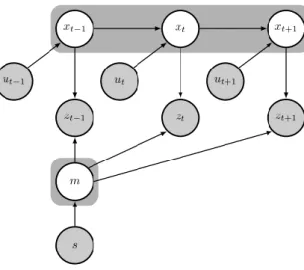
du véhicule (ou de le poser en mode SLAM en ligne) et en même temps de cartographier l’environnement voisin à partir des entrées des capteurs du véhicule. Une représentation graphique du problème SLAM complet et du problème SLAM en ligne est présentée aux figures 2.6a et 2.6b, respectivement. Dans le problème du SLAM complet, l’algorithme est supposé estimer la trajectoire entière du véhicule, formulée par une liste de ses poses sur le pas de temps k: x_k avec des capteurs lisant z_k, une entrée de commande u_k et construisant en même temps la carte m environnement. Cette tâche exigeante devient de plus en plus complexe avec le temps et il est difficile d’être gérée en temps réel. L'idée du SLAM en ligne, censé être fait en temps réel, est ensuite introduite. Le SLAM en ligne estimera uniquement la pose du véhicule actuel, ce qui réduira efficacement la complexité du problème. Vous trouverez un aperçu de la tendance actuelle du SLAM dans (Bresson et al. 2017). Compte tenu de la précision des capteurs laser et du potentiel du SLAM, la combinaison de LiDAR-SLAM devient rapidement l’une des clés pour des véhicules totalement autonomes. Au fil des ans, les techniques d’estimation dans SLAM peuvent être classées en approches basées sur les filtres et en approches basées sur l’optimisation.
L'idée de base des approches basées sur les filtres provient du filtrage bayésien et comprend deux étapes: la prévision et l'observation. Lors de la première étape, une prédiction de la pose et de la carte du véhicule est effectuée à l’aide d’un modèle dynamique des véhicules. Le modèle pour faire correspondre une observation à la carte s'appelle un modèle d'observation. Les deux branches principales de cette approche sont les filtres étendus de Kalman et les filtres à particules SLAM.
Le SLAM basé sur l'optimisation (M. Liu et al. 2012) est également un algorithme en deux étapes itératives. La première étape identifie les contraintes du problème en fonction des données du capteur. Cela se fait en faisant correspondre les nouvelles observations à la carte. La deuxième étape calcule la pose du véhicule et la carte en fonction des contraintes identifiées. Les techniques basées sur la vision pour SLAM sont plus susceptibles d'utiliser cette approche, les techniques basées sur le laser sont également incluses dans la classe d'algorithme Graph-SLAM.
Une autre approche notable pour la localisation de véhicules est la technique basée sur des capteurs visuels. En utilisant un système de vision et des algorithmes de traitement d'image, un véhicule peut se localiser correctement dans un environnement pré-mappé. Cette approche est sensible aux conditions d'éclairage, ce qui en fait un candidat idéal pour la localisation à l'intérieur. La plupart des approches de localisation basées sur des caméras s'inscrivent dans des
Chapter 2: Intelligent Vehicles Localization ---
types de méthodes basées sur l'appariement de cartes. Dans ces approches, une carte détaillée de l'environnement est construite dans une phase hors ligne. Sur la base de l'entrée de caméra de phase en ligne et de la carte hors ligne, l'emplacement du véhicule est calculé. Semblable au laser SLAM, le SLAM visuel est une approche populaire pour la localisation de véhicules intelligents. Le concept SLAM reste le même que dans le SLAM laser, mais dans ce cas, un ensemble de caméras est monté sur le véhicule pour capturer non seulement des images mais également pour mesurer la profondeur de la scène.
Le calcul à mort est un processus d’estimation de la pose actuelle d’un véhicule à l’aide d’une pose préalablement déterminée et du modèle dynamique du véhicule. À l’origine, il s’agissait d’une approche développée pour les applications marines et qui est maintenant utilisée dans divers domaines tels que la navigation aérienne, le suivi des piétons ou la navigation autonome par robot. L'algorithme de calcul à rebours utilise différentes configurations de capteurs. Le calcul à mort avec unités de mesure inertielle (IMU) est largement utilisé dans la navigation de véhicules spatiaux, de navires de mer ou de véhicules terrestres. IMU a généralement des gyroscopes à trois axes et des accélérateurs pour mesurer la vitesse angulaire et la vitesse de déplacement de l'objet attaché.
L'un des inconvénients du GPS est sa disponibilité dans les scénarios urbains. Le plus souvent, les signaux GPS sont perdus ou mal reçus dans un tunnel, un parking ou lorsque le récepteur est entouré de bâtiments, obstruant ainsi la visibilité directe des satellites. Les signaux GPS standard souffrent également de l'effet de trajets multiples qui pourrait entraîner une erreur de localisation supplémentaire de 8 m (Kos, Markezic et Pokrajcic 2010). Néanmoins, le GPS (et les autres GNSS) joue un rôle essentiel dans la localisation, en particulier à l’échelle mondiale, car il s’agit du seul système de positionnement qui affiche directement dans le repère global. Sans ces coordonnées de référence globales, chaque véhicule intelligent fonctionnera selon ses propres coordonnées locales. Aucune communication ni coopération n'est possible.
Au cours des dernières années, la communauté de recherche sur les véhicules intelligents a développé plusieurs systèmes dédiés à la localisation dans les zones interdites de GPS en général et les parkings en particulier. En raison du manque de signaux GPS, la plupart des solutions de localisation dans ce domaine se situent au niveau de la localisation locale. En fonction du choix du système de coordonnées de référence, ces travaux peuvent être classés en deux classes: méthodes de localisation absolue (ou basées sur une carte) et méthodes de localisation relative (autocentrées, sans carte). Les travaux récents des deux classes seront
Chapter 2: Intelligent Vehicles Localization ---
Nguyen Dinh Van - January 2019 14
Dans l'approche du positionnement absolu, il est nécessaire qu'une carte de l'environnement soit connue au préalable par le véhicule. Cette carte comprend deux composants principaux: les objets statiques qui contribuent à la structure de la carte (route, murs, portes, etc.) et les objets dynamiques qui constituent des obstacles dans l'environnement (autres véhicules, piétons, etc. .) Selon la solution, la carte peut contenir les deux ou uniquement des objets statiques.
Contrairement à la localisation absolue, la localisation relative ne nécessite pas une carte détaillée de l'environnement. L’approche vise à estimer la position du véhicule par rapport aux objets locaux environnants tels que les autres véhicules, le marquage des voies, etc.
Parmi ces deux approches, la méthode cartographique semble beaucoup plus précise. Un système bien défini peut localiser des véhicules avec une précision allant jusqu'à 0,1 m. Toutefois, pour ceux qui disposent d’une carte détaillée de l’environnement, la résolution et la précision des informations cartographiques ont une influence considérable sur l’erreur de localisation. Malheureusement, plus la résolution est élevée, plus la solution est complexe et moins évolutive. Ainsi, une nouvelle solution pour ce scénario est requise.
2.1 Overview of Intelligent Vehicles Localization
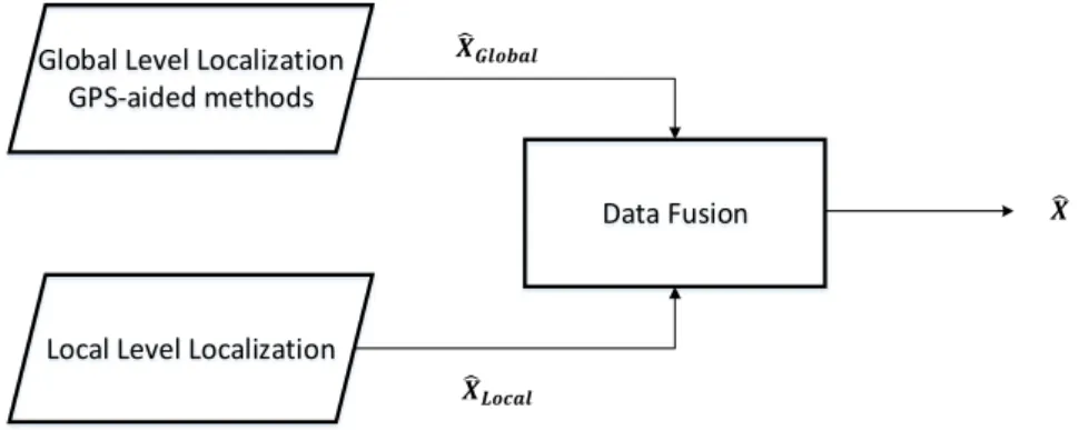
Localization is a task of determining an object’s pose (e.g. coordinate, heading angle) or the spatial relationship among objects. This is an essential task for an autonomous navigation a vehicle has to achieve (Eskandarian 2012). Only by knowing precisely the location of itself in either a local or a global map, then action such as path planning or obstacles avoidance can be carried out. Often, this task is accomplished through a set of dedicated sensors (on vehicle sensors or environment sensors). The process of combining these sensors inputs to infer the vehicle’s position is called sensor fusion.
There are two levels of localization for intelligent vehicles: global level and local level. The global level localization often results in the vehicle’s pose in the global coordinates frame (e.g. WGS84, NAVD88, ETRS89, etc.) and offers a broad view of vehicle’s location and context. The accuracy of this localization level is not required to be in the order of centimetres. Instead, a raw but stable estimation of the vehicle’s absolute location is sufficient. One example of this level of localization is GNSS-based localization methods. The local level of localization is usually expressed in an arbitrary local reference coordinate frame. This level of localization is responsible for accurately determining the spatial relationship of the vehicle with other objects in the environment. Some notable methods for this level of localization are laser-SLAM, camera-based map matching, dead-reckoning, etc.
Chapter 2: Intelligent Vehicles Localization ---
Data Fusion Global Level Localization
GPS-aided methods
Local Level Localization
𝑿𝑮𝒍𝒐𝒃𝒂𝒍
𝑿𝑳𝒐𝒄𝒂𝒍
𝑿
Figure 2.1 Fusion of localization systems
In an ideal intelligent vehicle, a localization system should be a fusion of both levels of localization as in Figure 2.1. The global level of localization returns the estimated pose 𝑿𝑮𝒍𝒐𝒃𝒂𝒍 in the global coordinates frame while the local level often output estimation 𝑿𝑳𝒐𝒄𝒂𝒍 in a local
coordinates frame. The two estimations are then fused to deliver the final absolute pose of the vehicle. In practice, most localization systems consist of a GPS-like system combined to another local positioning method such as a SLAM based system. The final localization estimation is often expressed in the global coordinate standard.
In this chapter, a quick review of localization methods for intelligent vehicles is presented. Both local and global levels of localization methods are studied and more specifically, those that are dedicated to the GPS-denied environment.
2.2 GPS-based Localization
The GPS-based localization method is a class of localization methods that makes use of satellite signals to determine 3D position information of the receiver in a global reference (such as WGS84). The term GPS refers to Global Positioning System which is governed by the United States of America. There are others Global Navigation Satellite Systems (GNSS) such as GLONASS (Russia), Galileo (Europe), and Beidou (China). To simplify the problem, the thesis will focus on GPS performance as a representative for other GNSSs.
The principle of computing the receiver location is based on knowing the positions of the satellites then deducing the respective “pseudo-ranges” from those satellites to the receiver as in Figure 2.2. Here, the term “pseudo-range” refers to the distance calculated from satellites to the mobile receiver. Since satellites are constantly moving, this distance is not a fixed value. To calculate the 3D position of a receiver, at least four satellites are required. An overview of the GPS system can be found in (Hofmann-Wellenhof, Lichtenegger, and Wasle 2018).
Chapter 2: Intelligent Vehicles Localization ---
Nguyen Dinh Van - January 2019 16
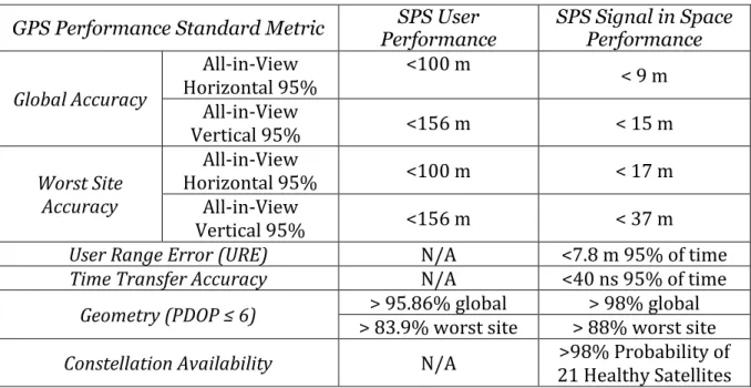
There are two level of GPS services namely Standard Positioning Service (SPS) and Precise Positioning Service (PPS). While SPS is accessible by public users, high precision PPS is only accessible by authorized users (military personnel, government agents). Summary of SPS and PPS performance are shown in Table 1 and Table 2.
{𝑥𝑠1, 𝑦𝑠1, 𝑧𝑠1}
{𝑥𝑠2, 𝑦𝑠2, 𝑧𝑠2} {𝑥𝑠3, 𝑦𝑠3, 𝑧𝑠3}
{𝑥𝑠4, 𝑦𝑠4, 𝑧𝑠4}
{𝑥 , 𝑦 , 𝑧 }
Figure 2.2 GPS principle
Table 1 Service performance standard for SPS (Department Of Defense 2008; “GPS Performances - Navipedia” 2018)
GPS Performance Standard Metric Performance SPS User SPS Signal in Space Performance Global Accuracy All-in-View Horizontal 95% <100 m < 9 m All-in-View Vertical 95% <156 m < 15 m Worst Site Accuracy All-in-View Horizontal 95% <100 m < 17 m All-in-View Vertical 95% <156 m < 37 m
User Range Error (URE) N/A <7.8 m 95% of time
Time Transfer Accuracy N/A <40 ns 95% of time
Geometry (PDOP ≤ 6) > 83.9% worst site > 95.86% global > 88% worst site > 98% global Constellation Availability N/A 21 Healthy Satellites >98% Probability of In general, SPS provides 7.8m of maximum localization error in 95% of the time and PPS offers a better accuracy with 5.9m of maximum localization error in 95% of the time. Also, vertical accuracy is expected to be lower than horizontal accuracy in all GPS measurements.
Table 2 Service performance standard for PPS (“GPS Performances - Navipedia” 2018; GPS Directorate 2007)
Chapter 2: Intelligent Vehicles Localization ---
GPS Performance Standard Metric SPS User
Performance SPS Signal in Space Performance Global Accuracy All-in-View Horizontal 95% <36 m < 13 m All-in-View Vertical 95% <77 m < 22m
User Range Error (URE) N/A <5.9 m 95% of time
Time Transfer Accuracy N/A <40 ns 95% of time
Geometry (PDOP ≤ 6) > 95.7% global > 98% global
Constellation Availability N/A 21 Healthy Satellites >98% Probability of There are ways to further improve GPS accuracy with a technique called Differential GPS (DGPS). The technique enhances GPS position using an accurately-surveyed position known as the reference station. Nowadays, most commercial GPS units offer DGPS data to some extent using world-wide available reference stations. Depending on the location as well as the distance to a reference station, DGPS accuracy is in the order of 1m (1 sigma) for users (“Differential GNSS - Navipedia” 2018) . The study presented by (Kuter and Kuter 2010) shows that an estimated Root Mean Squared Errors (RMSE) of GPS and DGPS are roughly 6.413m and 2.587m respectively. In the best case scenario, a highly accurate DGPS solution known as Real Time Kinematic GPS (RTK GPS) can deliver up to few centimetres of accuracy. However, the method requires dedicated base stations, sensors, continuous GPS signals and an excessive price for deploying and maintaining. This makes the RTK not suitable for most urban application (“Real Time Kinematics - Navipedia” 2018).
Similar to the US, the European Union also develop a global positioning system called Galileo to provide an independent high precision global positioning system for the European nations. The system is supposed to help the EU countries not to rely on China’s BeiDou, Russian GLONASS or more significantly, the United States GPS. Under good conditions such as fully function satellites (up to 30 units), clear vision from receiver to satellites, etc. the free open access for navigation of the Galileo system within the EU border is expected to be around 4 meter of precision (“Galileo General Introduction - Navipedia” 2018). However, the much expected feature of the Galileo system lies in the commercial service. Its architecture is demonstrated in Figure 2.3. With this paid service, the global positioning accuracy is expected to be at decimetres (Ignacio, Irma, and Guillermo 2015). To achieve this level of accuracy, the system will either make use of the Real-time Kinematic concept (RTK) or the precise point positioning (PPP). While the RTK is almost instantly return high precision positioning result,
Chapter 2: Intelligent Vehicles Localization ---
Nguyen Dinh Van - January 2019 18
PPP requires 15-30 minutes of the initialization. Experiments results with the high precision commercial positioning service are shown in Figure 2.4.
Figure 2.3 The Galileo satellites navigation system commercial service architecture (Fernández-Hernández et al. 2018)
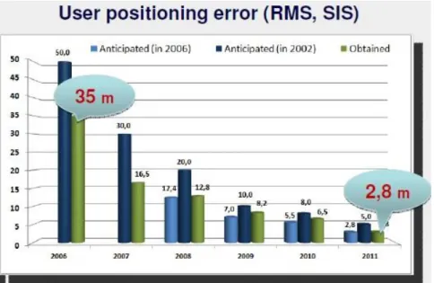
Another worth to mention global positioning system is the GLONASS developed by Russia in 1980s. By 2010, the GLONASS has covered the entire Russia territory then after October 2011, the global coverage is achieved. The evolution of the GLONASS positioning accuracy is shown in Figure 2.5. Up to now, under static sky, the GLONASS accuracy for public access is as good as 2.8 meters.
Chapter 2: Intelligent Vehicles Localization ---
Figure 2.4 The kinematic high precision positioning results of Galileo (Ignacio, Irma, and Guillermo 2015)
Chapter 2: Intelligent Vehicles Localization ---
Nguyen Dinh Van - January 2019 20
Table 3 Comparison between global positioning systems (Hofmann-Wellenhof, Lichtenegger, and Wasle 2018)
System BeiDou Galileo GLONASS GPS
Owner China EU Russia United States
Coverage Global by 2020 Regional, Global by 2020 Global Global Satellites 5 (+ 30) 14 operational 24 by design 24 operational 24 by design 31 operational 24 by design Precision 0.1m Private 10m Public 0.01m Private 4m Public 4 – 7m 0.01m Private 2- 4m Public
2.3 Laser-based Localization
Laser-based localization methods are usually assigned to the local localization category. Using a rangefinder technique based on laser beams, the sensor accurately estimates the distance to other objects in the environment. An important form of laser sensor setup is LiDAR (James Eddy 2017) (Light Detection and Ranging) which fires continuously laser beams to the environment. This helps to estimate the distance to surrounding obstacles and allows to perform a mapping of the environment at a high resolution.
When it comes to laser sensor, the majority of its localization algorithms involve solving entirely or partially a Simultaneous Localization and Mapping (SLAM) problem (Smith and Cheeseman 2018), (Durrant-Whyte and Bailey 2006), (Dellaert et al. 2018).The SLAM objective is to estimate the vehicle’s trajectory (or pose in online SLAM) and at the same time to map the neighbouring environment given inputs from the vehicle’s sensors. A graphical representation of the full SLAM and online SLAM problem is shown in Figure 2.6a and Figure 2.6b respectively.
Figure 2.6 Graphical representation of (a) Full SLAM problem; (b) Online SLAM problem (Bresson et al. 2017)
Chapter 2: Intelligent Vehicles Localization ---
In the full SLAM problem, the algorithm is supposed to estimate the whole trajectory of the vehicle formulated by a list of its poses over time step k: 𝑥𝑘 given sensors reading 𝑧𝑘, control input 𝑢𝑘 and at the same time building the map 𝑚 of the environment. This demanding task
becomes more and more complex over time and it is difficult to be handled in real time. The idea of online SLAM, which is supposed to be done in real time, is then introduced. Online SLAM will only estimate the current vehicle’s pose thus effectively reduce the complexity of the problem. An overview of the current trend in SLAM can be found in (Bresson et al. 2017). Given the accuracy of laser sensors and the potential of SLAM, the combination of LiDAR-SLAM quickly becomes one of the keys towards fully autonomous vehicles. Over the years, the techniques of estimation in SLAM can be categorized into filter-based approaches and optimization-based approaches.
2.3.1 Filter-based Laser SLAM
The core idea of filter-based approaches comes from Bayesian filtering and consists of two steps: prediction and observation. In the first step, a prediction of the vehicle’s pose and map state is made using a dynamic model of the vehicles with control inputs 𝑢𝑘. Having this prediction, a correction is made based on the current observation from sensors inputs 𝑧𝑘. The
model to match an observation with the map is called an observation model. Two major branches in this approach are Extended Kalman Filter and Particle Filter based SLAM. Extended Kalman Filter (EKF) (Fujii 2018) is a non-linear filter that adds a linearization step for a non-linear model. The linearization is performed around the current estimation state by a first-order of Taylor expansion. The result of this filtering method is converged as long as the linearization process is made around the true state. However, in practice, estimated states can fall well outside of true values uncertainty. This causes consistency issues for EKF-SLAM (Julier and Uhlmann 2001),(Bar-Shalom, Li, and Kirubarajan 2001). Still, with a well-designed estimation model, the EKF-SLAM is proved to be a success in a constrained situation such as urban environments. This makes EFK-SLAM one of the most widely studied solution (Xie et al. 2011; Elfes 2013; Weiss, Schiele, and Dietmayer 2007).
Since EKF-SLAM estimates a vehicle pose based on a map of landmarks, when the number of landmarks increases, the complexity of EFK-SLAM increases exponentially. Thus, FastSLAM is introduced with an idea of using Particle Filter as a tool to reduce complexity and consequently allow SLAM to run in real time. In particle filter, two states of the filter are:
Chapter 2: Intelligent Vehicles Localization ---
Nguyen Dinh Van - January 2019 22
where with each particle, a likelihood function is calculated as the score of how likely this particle is the true state. Thus, by limiting the solution space within N particles, the complexity of Particle Filter (PF) SLAM is then Ο(Nlog 𝐿) where L is number of landmarks in the map. In contrast, the complexity of EKF-SLAM is Ο(𝐿2). When the number of landmarks increases, the advantage of PF-SLAM becomes more and more significant. Works in (Hahnel et al. 2018; Mohan and MadhavaKrishna 2010; Montemerlo et al. 2018) demonstrates FastSLAM approach which can work in a large scale environment and (Reineking and Clemens 2013; Trehard et al. 2014) implements FastSLAM using evidential theory instead of a classical probabilistic model. Results of the approach using evidential SLAM and particle filter is shown in Figure 2.7.
Chapter 2: Intelligent Vehicles Localization ---
2.3.2 Optimization-based Laser SLAM
Optimization-based SLAM (M. Liu et al. 2012) is also a two iterative steps algorithm. The first step identifies constraints of the problem based on sensor data. This is done by matching between new observations and the map. The second step computes the vehicle pose and the map given the identified constraints. Vision-based techniques for SLAM are more likely to use this approach, laser-based techniques are also included within Graph-SLAM algorithm class. Graph-SLAM is a graphical representation of Bayesian SLAM. Based on this representation, a matrix of the relationship between landmarks and vehicles’ poses can be built and act as an optimization framework. An example of Graph-SLAM can be found in (Pierzchała, Giguère, and Astrup 2018) where a combination of Velodyne VLP 16, GPS, IMU and Stereo Camera are used to solve SLAM problem in a large scale of a forest. The map resulted from this work were evaluated using the relative distance between trees which is around 2.38cm of error (Figure 2.8).
Figure 2.8 GraphSLAM visualization of large scale forest mapping (Pierzchała, Giguère, and Astrup 2018)
Another work is mentioned in (Carlson, Thorpe, and Browning 2010) where an attempt to map a large scale urban environment using SLAM and GPS reference is made. Demonstrated results are in Figure 2.9.
Chapter 2: Intelligent Vehicles Localization ---
Nguyen Dinh Van - January 2019 24
Figure 2.9 GPS-aided SLAM for large scale uban mapping (Carlson, Thorpe, and Browning 2010)
While promising results were shown in studies for this method, it is worth to mention that without absolute correction such as GPS, camera-based landmark detection or a pre-defined map, it is not possible for SLAM to achieve this high precision in mapping and localization.
2.4 Vision-based Localization
Another notable approach for vehicle localization is visual sensors based technique. Using a vision system and image processing algorithms, a vehicle can correctly localize itself within a pre-mapped environment. This approach is sensitive to lighting conditions making it a suitable candidate for indoor localization.
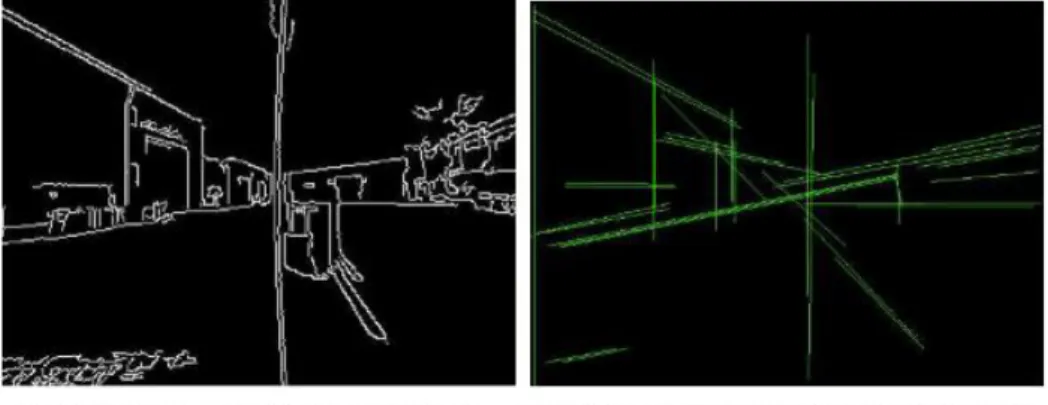
Most of camera-based localization approaches fall into map-matching based method types. In these approaches, a detailed map of the environment is built in an offline phase. Based on online phase camera input and the offline map, the location of the vehicle is calculated. The study in (Borges et al. 2010) shows a combination of laser-edged map and vision images matching method for industrial vehicles. The system first needs an edge-filtered map of the environment from a 3D point cloud of laser sensors in the offline phase as showed in Figure 2.10. It then processes to detect edge in online phase camera input for map-matching and consequently vehicle localizing. (Figure 2.11). Depending on weather and lighting conditions, the solution reaches an average localization accuracy of 0.875m for the best scenarios and 1.390m for the worst.
Chapter 2: Intelligent Vehicles Localization ---
Figure 2.10 Edge-filtered map of the environment (Borges et al. 2010)
Figure 2.11 Camera image to edge image transformation (Borges et al. 2010)
Similar to Laser SLAM, visual SLAM is a popular approach for intelligent vehicles localization. The SLAM concept remains the same as in the laser SLAM but in this case a set of cameras is mounted on the vehicle to capture not only images but also to measure the depth of the scene. An interesting research work proposed by (Shi et al. 2012) consists of a fusion of GPS and aided visual SLAM methods, which does not use any additional sensor. The system however consists of six calibrated fish eyes cameras with a dual-frequency GPS receiver. In an offline mapping phase, the GPS observation is supported by CORS RTK technology which has an accuracy within 0.02m. Based on this map, the online localization method yields an accurate position with an average error under 0.067m. Note that this paper uses only 8 checkpoints as an evaluation ground truth and no lighting condition is mentioned.
2.5 Dead-Reckoning
Dead-reckoning is a process of estimating the current pose of a vehicle using a previously determined pose and the vehicle’s dynamic model. Initially, it was an approach developed for
Chapter 2: Intelligent Vehicles Localization ---
Nguyen Dinh Van - January 2019 26
marine applications and has now been used in a variety of fields such as air navigation, pedestrian tracking or autonomous robot navigation.
The dead-reckoning algorithm makes use of different sensor configurations. Dead-reckoning with Inertial Measurement Units (IMU) is widely used in the navigation of spacecraft, marine ships or landline vehicles. IMU typically has three-axis gyroscopes and accelerators to measure angular and displacement velocity of the attached object.
Depending on the precision of sensors inside the IMU (gyroscopes and accelerators), the dead-reckoning can incrementally estimate the local pose of the vehicle using a pre-defined dynamic model. This, however, results in the accumulated error over time as inaccuracy in each measurement adds up. It is almost impossible to correct this error by the system itself as there is no absolute reference source. An attempt to fix this problem using dual drive system and modelling of expected accumulated error is found in (Borenstein 1995), yet the result is limited. Consequently, almost all dead-reckoning solutions are now used in fusion with other localization techniques such as GPS (Fouque et al. 2008), laser-SLAM (Akai et al. 2017) or vision-based (Vivacqua et al. 2018). The idea is to incorporate an absolute reference to regularly correct the accumulated error results from the dead-reckoning process. An example of a solution to correct dead-reckoning using static map can be found in (Fouque et al. 2008). The result of this solution is shown in Figure 2.12. It can be seen in the figure that even with correction from static map and some GPS injection, the dead-reckoning still has a large accumulated error over time (around 22m).
In conclusion, the general accuracy estimation of this method is large. It heavily depends on the precision of IMU components, the dynamic model of the vehicle as well as any possible correction applied. A carefully designed dead-reckoning process using high precision sensors could be extremely accurate in a close range. This makes dead-reckoning a preferable solution for indoor localization (Z. Liu et al. 2017; Huijie Chen, Li, and Wang 2018).
Chapter 2: Intelligent Vehicles Localization ---
Figure 2.12 Dead-reckoning and static map (Fouque et al. 2008)
2.6 Intelligent Vehicles Localization in GPS-denied Environments
One of the drawbacks of GPS is its availability in urban scenarios. More often, GPS signals are lost or poorly received in a tunnel, a carpark or when the receiver is surrounded by buildings thus obstructs line-of-sight to satellites. The standard GPS signals also suffer from the multi-path effect which could result in additional 8m of error in localization (Kos, Markezic, and Pokrajcic 2010). Still, GPS (and other GNSSs) plays a vital role in localization especially at the global scale as it is the only positioning system that directly outputs in the global coordinate frame. Without this global reference coordinates, each intelligent vehicle will work on its own local coordinates hence no communication or cooperation is possible.
In the last few years, the research community in Intelligent Vehicles has been developing several dedicated systems for localization in GPS-denied areas in general and carparks in particular. Due to the lack of GPS signals, most of the solutions for localization in this domain fall into the local localization level. Depending on the choice of the reference coordinate system, these works can be categorized into two classes: absolute localization (or map-based) methods and relative localization (self-centric, without a map) methods. The two classes’ recent works will be studied in the following sections.
2.6.1 Absolute Localization
In the absolute positioning approach, it is required that a map of the environment is known beforehand by the vehicle. In this map, there are two main components: static objects which