Science Arts & Métiers (SAM)
is an open access repository that collects the work of Arts et Métiers Institute of Technology researchers and makes it freely available over the web where possible.
This is an author-deposited version published in: https://sam.ensam.eu
Handle ID: .http://hdl.handle.net/10985/9752
To cite this version :
Patrice PEYRE, Laurent BERTHE, Morgan DAL, Sébastien POUZET, Pierre SALLAMAND, Iryna TOMASHCHUK - Generation and characterization of T40/A5754 interfaces with lasers - Journal of Materials Processing Technology - Vol. 214, p.1946-1953 - 2014
Any correspondence concerning this service should be sent to the repository Administrator : [email protected]
Generation and characterization of T40/A5754 interfaces with lasers
Patrice Peyre*, Laurent Berthe, Morgan Dal, Sébastien Pouzet
PIMM Laboratory, UMR 8006 CNRS – Arts et Métiers ParisTech 151 Bd de l'Hôpital, 75013 Paris, France
Pierre Sallamand, Iryna Tomashuk
LTM – ICB Laboratory, UMR 6303 CNRS – Université de Bourgogne 12 rue de la fonderie, 71200 Le Creusot
* [email protected], tel : 33(1) 71 93 65 44
Keywords: dissimilar joining, laser, shock waves, titanium, aluminum
Abstract
Laser-induced reactive wetting and brazing of T40 titanium with A5754 aluminum alloy with 1.5 mm thickness was carried out in lap-joint configuration, with or without the use of Al5Si filler wire. A 2.4 mm diameter laser spot was positioned on the aluminum side to provoke spreading and wetting of the lower titanium sheet, with relatively low scanning speeds (0.1 to 0.6 m/min). Process conditions did not play a very significant role on mechanical strengths, which were shown to reach 250-300 N/mm on a large range of laser power and scanning speeds. In all cases considered, the fracture during tensile testing occurred next to the TiAl3 interface, but in the aluminum fusion zone. In a second step, we have
investigated the interfacial resistance with the LASAT bond strength tester, based upon the generation and propagation of laser-induced shock waves. This allowed us estimating a uniaxial bond strength of 0.68 GPa for the T40/A5754 interface under dynamic loading conditions.
Introduction
The dissimilar joining of titanium and aluminum, despite many potential applications in several industries, is usually restrained by the bad metallurgical compatibility of the two materials, which exhibit a limited solubility of titanium in aluminum solid solution and the extensive formation of brittle intermetallic compounds such as TiAl3 as indicated by Gupta et al. (2003). This is particularly true when
joining is carried out in liquid regime which promotes Ti-Al inter-diffusion. For this reason, many recent investigations like Chen et al. (2009-1) or Liao et al. (2010) have considered Ti-Al joining at a solid state with friction stir welding. Similarly, Kahraman et al. (2007) have carried out successfully explosive bonding assemblies without fusion of the metals. Other trials have used brazing processes where the titanium side is kept solid whereas only the aluminum side is molten. For instance, Chen et al (2009-2)
have proposed a specific Y-shape configuration for assembling Ti6Al4V and Al6Mg alloy with laser in welding-brazing regime whereas Ma et al. (2013) have carried out tungsten arc butt-joining with Al-Si filler wire. Considering brazing processes, many factors need to be addressed: (1) some of them concern the wettability of titanium by liquid aluminum pools and the potential influence of non-melted Al2O3
oxides floating on the melt-pools spreading, (2) other ones come from the influence of the TiAl3
interfacial layer thickness on final mechanical resistance. Preliminary investigations like those by Chen et al. (2009-2) have pointed out the detrimental effect of intermetallic (IM) thicknesses superior to 5 µm on interfacial strength. However, as homogeneous IM layers are usually required for enhancing mechanical behavior, this implies the generation of homogeneous temperature profiles T=f(x, y, t) between solid titanium and liquid aluminum, with well-controlled temperature levels to favor Ti to Al diffusion, without promoting Ti fusion. In this context, lasers appear to be promising candidates for brazing Ti with Al, because of the large range of beam shapes (circular, rectangular) and spatial profiles (uniform, top-hat, annular) that allow optimizing interfacial conditions by selecting optimal heat source amplitude and distribution.
Usually, brazing was carried out with a classical conduction regime. However, with the objective of increasing the scanning speed, Kreimeyer et al. (2005) have optimized butt-brazing of 2 mm-thick Ti6Al4V to AA6016 sheets with the use of a laser-induced key-hole positioned in the aluminum side, without using fluxing of the interface, and with laser offsets of 0.3 to 1 mm. With the use of a combined numerical-experimental approach, they have also defined an optimum process window to induce sufficiently thick (0.7-1.5 µm) TiAl3 intermetallic phases in key-hole regime. Similar experiments were
shown recently by Song et al. (2013) considering a AA6061 alloy. In both cases, they have obtained 10 % lower mechanical resistance during tensile testing than the base aluminum alloy. More complex geometrical configurations were also tested. For instance, Vaidya et al. (2010) have also considered a butt-brazing condition, but with specifically designed u-shape AA 6056 samples, and a split-beam laser brazing to ensure a symmetrical contact with Ti6Al4V sheets. Last, Chen et al (2009) have investigated the effect of a rectangular laser spot on the dissimilar assembly of Ti6Al4V to 5A06 with V-shape groove and Al12Si eutectic filler wire. In this condition, the molten filler wire wets the titanium side and is mixed with the aluminum molten side to form a brazing-welding process.
In all the studies available in the literature, the interfacial layer between Al and Ti was formed by a near stoichiometric TiAl3 serrated intermetallic with the possible occurrence of more complex compounds
such as Ti7Al5Si12 when additional Al-Si material was used during the welding-brazing process, as
evidenced by Chen el al. (2011).
Following these works, we have selected a rather simple lap-joint configuration to form Ti/Al interfaces by a laser-induced melting in conduction regime (≈ without key-hole formation), at relatively low scanning speed in order to favor liquid aluminum – solid titanium inter-diffusion. We also have selected two materials: a low alloyed T40 titanium alloy, and an Al-Mg alloy (A5754) for which no preliminary study on Ti/Al joining exists. Moreover, and for the first time, such Ti/Al interfaces were used for testing the LASAT bond strength technique on dissimilar joints.
1. Materials and experimental conditions
1.1. Materials
T40 titanium alloy (Ti-0.1 Fe – 0.01 N) and A5754-H111 (Al-3.2 Mg-0.4 Fe- 0.4 Si- 0.5 Mn- 0.3 Cr) aluminum alloy were selected to evaluate the potential of the laser-induced reactive wetting technique in overlap condition, with or without using A4043 (Al-5Si) filler wire. 100 mm x 100 mm x 1.5 mm sheets
were used for assemblies, with a 1.2 mm diameter wire for A4043. Thermo-physical properties of the three alloys considered are presented here below (table 1).
TF (K) Cp (J/kg.K) (kg/m3) k0 (W/m.K)
YS (MPa) UTS (MPa) E (GPa)
T40 1930 453 4420 25 350 450 104
A5754 900 628 2690 90 110 208 70
A4043 820 628 2710 100 120 240 69
Table 1 : thermo-physical and mechanical properties of T40 titanium alloy and AA 5754 aluminium alloy
1.2. Laser brazing conditions
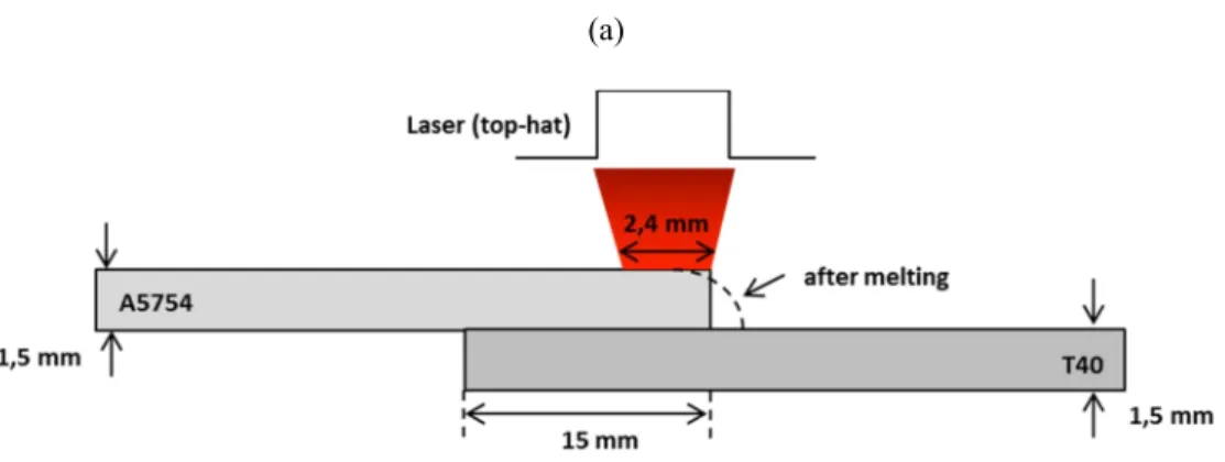
Ti to Al assemblies were carried out in overlap condition, with a 15 mm overlap between aluminum and titanium, and the aluminum sheet positioned on top of the titanium (Figure 1). A 2.4 mm top-hat laser irradiation (10 kW Yb : YAG disk laser operating at 1.03 µm), obtained with a 0.4 mm optical fiber, and a factor-6 magnification (100 mm collimating lens, and 600 mm focusing lens) was used to melt the aluminum, and make it spread on the titanium surface. A vertical clamping applied on two points was used in order limit deformations occurring during the brazing process, and to ensure as good as possible thermal contact between the two overlapped sheets. Prior to welding, both titanium and aluminum surfaces were fluxed to improve wetting phenomena and enhance Ti to Al diffusion by provoking a reduction of alumina Al2O3. This global approach is rather similar to the one used in a previous
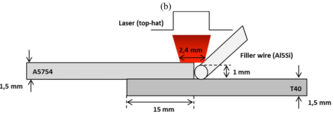
publication by Peyre et al. (2007) on aluminum-steel joining. Most of the assemblies were carried out without additive material, but a few tests were made with Al-5Si (5043) filler wire to estimate the influence of Si on interface formation. Experimental conditions are summarized in Table 2. To improve laser-Aluminum coupling and increase the absorptivity at =1.03 µm, a 5-10 µm organic black paint was sprayed on the top aluminum surface. With the back paint, the absorptivity was estimated to increase from 5 % to 40 %. After welding, the remaining black paint was removed with ethanol. A volume energy density /V (J/m3) (with = P/S and S= laser spot area (m²)) was considered as a major contributor to local heating and interface formation. Last, CCD camera observation of the welding scene was carried out at relatively low frequencies (100-200 Hz) with a Pixel Link camera, with the main objective of analyzing aluminum spreading.
P (W) V (m/min) /V (J/m3) Vwire (m/min)
Without filler wire 1500 - 4000 0.1 - 0.5 8.3 to 20.1010 - With A4043 filler wire 2000 - 2500 0.3 – 0.4 8.9 to 11.1010 1 – 2.6
Table 2 : Experimental laser brazing conditions
(b)
Figure 1: Schematic drawing of the experimental joining conditions (a) without filler wire, (b) with filler wire
1.3. Metallurgical and mechanical analysis of assemblies
After brazing, assemblies were analyzed as follows: (1) image scanning of the front and back surface of joints, (2) preparation of metallurgical cross-sections perpendicular to the joints, (3) analysis of joints and interfaces with optical and electronic microscopy (SEM-FEG Hitachi 4800 II), (4) Vickers hardness tests were carried on cross sections with a 100 g load, (5) tensile tests at d/dt = 10-3 s-1 on 20 mm wide samples (on each assembly, two tensile samples were machined), (6) SEM analysis of fractures surfaces.
1.4. The LASAT bond test
To investigate further the mechanical resistance of joints, a novel LASAT bond analysis technique, using laser-induced shock waves, was carried out. This recently developed technique, already tested by Berthe et al. (2011) for evaluating the bond strength of paints or ceramic coating, was applied for the first time to the characterization of dissimilar weld joints. The basic principle of LASAT test is to generate a uniaxial tensile stress near the Al-Ti interface by imparting a laser-induced shock wave at the surface of the titanium sheet with the use of a nanosecond pulsed laser (Continuum Powerlite Plus, 1.5 J – 10 ns – 10 Hz) operating in the 1-10 GW/cm² range, and using the crossing of incident and reflected release waves to induce a high level tensile state susceptible to break the interface above a threshold stress value th. In
turn, this technique allows obtaining the uniaxial bond strength under dynamic loading (near106 s-1). Additionally, with the use a VISAR (Velocity Interferometer System for Any Reflector) device composed of a laser beam probe and of a Michelson interferometer, it allows measuring free velocities Uf (m/s)
behind Ti/Al joints. This provides information about preliminary de-bonding phenomena that modify velocity time profiles Uf=f(t).
Moreover, finite element simulations of shock wave propagation in the Ti/Al system were carried out on AbaqusTM 6.9 explicit software, in order to determine numerically interfacial stresses =f(t). The laser-induced pressure loading applied on the T40 side was considered as a non-uniform spatial distribution of pressure (x, y, t) = 0. (1 - 0.5 x²/r²)0.5, as already identified by Peyre et al. (2012), and with a
maximum pressure value 0 directly dependent on laser power density (W/m²) according to Berthe et
al. (1997).
In the Abaqus 2D model (5 mm x 1 mm), axisymmetric elements CAX4R were considered, with a 25 µm x 3 µm size. Elastic-plastic properties of T40 and A5754 were considered according to Table 1, and including a strain-rate sensitivity in terms of a Johnson-Cook’s law. The interface between the two materials was considered as perfect, and no fracture criterion was used in this preliminary work whereas future investigations should use direct or cumulative fracture criteria.
2. Experimental results
2.1. Analysis of Ti/Al joints
The visual inspection of Ti/Al joints globally revealed a satisfactory aspect, despite the occurrence of ripples near the aluminum side (Figure 2), which seem to arise from a limited aluminum melt-pool flow, and the presence of Al2O3 non-melted layer remaining on the top surface of the liquid aluminum. This
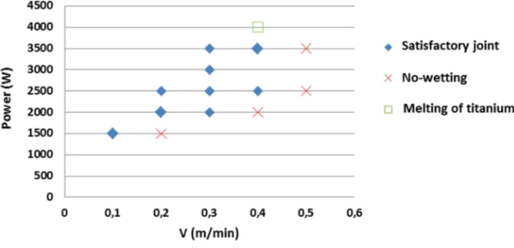
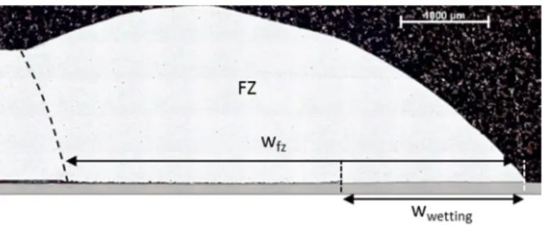
alumina layer was confirmed on CCD-cameras analysis on the whole melt-pool surface, except the irradiated zone which is expected to be hotter. For a large range of experimental conditions (Figure 3), apparently resistant assemblies were obtained, except for those carried out with insufficient laser power, for which wetting was inefficient, and those carried out with excessive laser power for which titanium melting occurred and provoked a macroscopic cracking when mixed with aluminum melt-pool. The width of the fusion zone Wfz of molten aluminum was found to be comprised between 5 mm and 7.5 mm,
depending on the volumetric energy /V. However, the width of interfacial bonding Wwetting, determined
on metallurgical cross-sections (Figure 4), is shown to be approximately 50 % to 70 % smaller than corresponding Wfz values. In spite of the use of fluxing to favor spreading of molten aluminum, a limited
wetting width is obtained, which is expected to decrease the mechanical resistance of joints.
Figure 2: top view of Ti/Al joints (without filler wire), (a) P = 2500 W, v = 0.4 m/min, Φ/v = 8.3.1010 J/m3, (b) P = 1500 W, v = 0.1 m/min, Φ/v = 20. 1010 J/m3
Figure 3: Results of Ti/Al joining tests versus scanning speed V and laser power P. At a given scanning speed, experiments carried out with insufficient power levels exhibit bad wetting whereas excessive laser power promote titanium melting. In-between these conditions, Ti/Al joints are satisfactory.
Figure 4: cross-section of a Ti-Al brazed joint without filler wire (P=3500 W, V=0.3 m/min). The wetted width Wwetting is
less than half the total fusion zone width Wfz of aluminum.
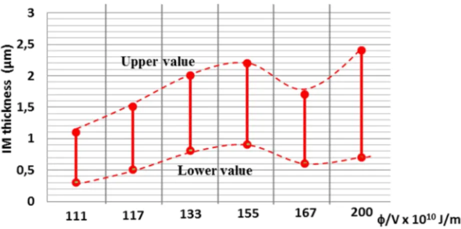
The SEM analysis of interfacial layers indicates that a serrate-shape TiAl3 intermetallic mostly forms
between solid titanium and liquid aluminum, with thickness ranging between 0.5 and 2.4 µm, which are constantly increasing with the volumetric energy /V (Figure 5). Such layers are thicker near the external edge of welds (near the maximum curvatur), where the laser-induced temperature profile was higher, and tend to decrease towards the internal part of the weld. For IM thickness below 0.5 µm, it seems that interfacial bonding is not high enough to accommodate thermal stresses and shrinkage induced during cooling. The resulting effect is that molten aluminum is debonded from titanium, even if titanium has been correctly wetted. Consequently, a minimum interfacial temperature Tint is necessary to ensure an
optimal bonding between Ti and Al. Compared with similar reactive wetting experiments carried out on Aluminum-steel joints by Peyre et al. (2007), interfacial layers were shown to be much thinner here, which reveals that diffusion coefficient of titanium in molten aluminum is smaller, or that passive layers formed on titanium or aluminum have not been sufficiently removed by fluxing, and have a played a role of solutal diffusion barrier.
EDS analysis were performed on fusion zones (FZ) and revealed a Mg depletion (-1.4 %), which was attributed to the high temperatures reached in molten pools that promoted Mg vaporization (Tv (Mg) =
1090°C).
Figure 5: SEM analysis of interfacial layers. TiAl3 intermetallic (IM) is mostly evidenced (SEM-EDS detection), with
IM thickness ranging between 0.5 µm and 2.4 µm. (a) and (b): P=3500 W – V= 0.3 m/min at the internal (a) or external (b) side of the interface. (c) IM thickness versus volumetric energy /V.
Reactive wetting experiments carried out with Al5Si filler wire were also analyzed and compared with assemblies realized without filler material. For similar experimental conditions (P, V), the use of a 5 % Si filler wire did not produce significant modifications neither to the welds geometry, nor to the IM layer thickness or stoechiometry. However, an increase of the wire speed Vwire, and of the Vwire/V ratio was
shown to induce a doming effect, mostly visible on cross-sections (Figure 6b
).
This dome-shape of the welds confirmed the rather poor wettability of titanium by molten aluminum for the experimental conditions considered here. Moreover, due to the offset of the laser spot towards the filler wire and the lower titanium sheet (the laser was half positioned on the wire and half on the Al sheet), and due to the oscillation of the wire, local fusions of the titanium occurred that did not interact with molten aluminum but are visible on top-views (Figure 6a).Last, EDS analysis performed on 5754 fusion zone (FZ) revealed, as expected, a Si enrichment (+1.5 %), and a Mg depletion (-1.3 %) compared with the as-received alloy.
Figure 6: Top view and cross-section of a Ti/Al assembly with Al-5Si filler wire (P=2500W, V=0.3 m/min, Vwire =1.5
m/min): a large doming effect is shown due to an excessive filler wire speed
2.2. Mechanical behavior of Al/Ti joints
First of all, hardness filiations were done on metallurgical cross-sections. A tiny reduction (-5 % = from 59 HV0.1 to 56 HV0.1) of Vickers Hardness was evidenced in the fusion zone of Ti/Al assemblies without
filler wire, compared with the initial A5754 alloy. This softening was mostly attributed to a small amount (-1 %) of vaporized Mg, which was confirmed by EDS measurements. With the use of 5% Si filler wire,
that increased the Si content in FZ up to 1-2 % Si, a solution-solid hardening (with possible contribution from precipitation hardening) was obtained, which increased the hardness up to 80-90 HV0.1. This
hardening was more pronounced with higher filler wire speeds that contributed to more significant increases of the Si content.
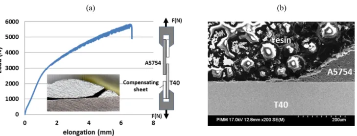
Tensile tests were carried out at 10-3 s-1 to estimate the mechanical resistance of joints. Due to the specific shape of overlap joints, some wedges were added to the samples (Figure 7a) to ensure as uniaxial as possible tensile loading. However, a tilt was systematically observed during the tests, so that tensile tests could not be considered as purely uniaxial. For this reason, results are not presented as () curves, but instead as (F (N), e (mm)) curves (Figure 7a). Consequently, mechanical strengths were given in terms of N/mm. For instance, a 5000 N maximum strength obtained on a 20 mm-wide specimen corresponded to a 250 N/mm linear resistance. We also could evidence a dependence of tensile resistance versus contact width Wwetting between Ti and Al sheets (Figure 8): resistances to failure increase with Wwetting then
saturate above 2.5 mm. Considering a maximum linear strength of 300 N/mm and a 2.5 mm wetting width, we can estimate a 120 MPa resistance for the joints, under a complex tensile/shear loading mode. Rather similar joint resistances were obtained with or without filler wire. Some 290 N/mm maximum values were obtained, and no clear dependence versus laser conditions (P, V) could be shown. For a single assembly, from which two tensile specimens were machined, a rather good reproducibility was obtained between the two tensile tests.
Because of the shape of the samples, special failure modes were shown. At the location where IM layer is too thin to ensure a contact between Al and Ti (end of Wwetting in Fig.4), a large stress concentration
usually provokes crack initiation. In a second step, the crack remains in the aluminum, but propagates at a low distance from interface. Last, in a 3rd and final step, and favored by the macroscopic tilt of the sample (compensation sheets are not efficient anymore), the fracture path deviates in the fusion zone of A5754 (Figure7b). In turn, such a failure came from a dual shear + tensile mode. An interesting point to notice is that Ti/Al interfacial layers (mostly TiAl3) did not crack during tensile tests and always remained sound,
whatever the process conditions. It was assumed that T40/TiAl3/A5754 interface was tight and highly
resistant. On a few samples (Figure 9), the near-interface was mostly sheared, resulting in a planar fracture aspect where cracks propagated.
(a) (b)
Figure 7: (a) Tensile curve obtained on a T40/A5754 joint without filler wire (P=3500 W, V=0.3 m/min), (b) cross-section of a fractured tensile specimen: the crack initiated at the triple point (inner end of the IM layer) where stress concentration are maximal, then propagated in the aluminium just above the IM layer, before fracturing the whole FZ
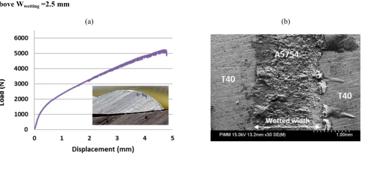
Figure 8: Dependence of the tensile resistance versus wetting width Wwetting. The resistance increases, then saturates
above Wwetting =2.5 mm
(a) (b)
Figure 9: (a) Tensile curve obtained on a T40/A5754 joint with filler wire (P=2000 W, V=0.3 m/min, Vwire=1.2
m/min),(b) a planar fracture surface is obtained, just above the IM layer: the molten A5754 remains sticked to the T40
3. Characterization of Ti/Al interfaces using the LASAT bond test
3.1. Preparation of specific Ti/Al samples
The use of LASAT bond test is possible with or without additional diagnostic:
(1) the first and simpler method consists in submitting the (coating + substrate) system to laser impacts of increasing power densities (W/m²) in order to estimate a threshold above which a visible decohesion occurs (like a bulging effect). Combined with finite element simulation, and assuming the pressure versus poser density dependence, this allow determining bond strengths; (2) the second method combines the first one, with a VISAR velocity diagnostic which is used for
probing the back free surface of the (coating + substrate) system. A change in the back free velocity time profile Uf=f(t) usually reveals the formation of voids or cracks in the system. This
second approach is more accurate and allows determining the first steps of the interfacial decohesion, even in cases where bulging cannot be directly evidenced.
The use of LASAT bond test combined with VISAR velocimetry requires several interface properties for being applied accurately: first, interfaces need to be planar and sufficiently large (a few mm) for performing VISAR measurements with a 0.3 mm diameter argon laser probe beam. Another important
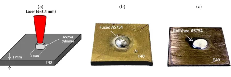
aspect to address is that front and back face of the assembly must be parallel so that shock wave propagations could accelerate the back free surface of the assembly in the direction opposite to the probe laser beam. Moreover, the thickness of the global assembly must be low enough to favor high interfacial applied stresses during the test. Consequently, our lap-joints were not found to be the best candidates for testing the LASAT technique on Ti/Al joints (interfacial zone was not wide enough, and the upper surface was convex). For this reason, a specific T40/A5754 assembly was realized in overlap condition, with a static laser irradiation on a (3 mm-diameter, 1.5 mm-height) A5754 laser-machined cylinder (Figure 10), allowing after melting and spreading to obtain a 5 mm wide axisymmetric interfacial area. After polishing the upper aluminum part, we could obtain two parallel faces, and a (0.4 mm A5754 / 0.4 mm T40) system which finally allowed us performing VISAR tests. For those tests, samples were mounted on a specific clamping device, with the aluminum side positioned towards the Ar probe laser, and the T40 side towards the shock generator laser (
Figure 11). The thermo-hydraulic finite element simulation of this wetting was also carried out and is available in Dal et al. (2013).
(a) (b) (c)
Figure 10: Fusion of a A5754 cylinder on a T40 sheet to prepare LASAT samples: (a) basic principle, (b) cylinder after melting and spreading, (c) A5754 cylinder and T40 sheet after melting-spreading and re-polishing on two sides: a system composed of 0.4 mm T40 / 0.4 mm 5754 is obtained, with a planar interface.
3.2. Experimental testing of Ti/Al interfaces
During the VISAR test, the Nd:YAG laser generates a high pressure plasma of 0 amplitude on T40,
which globally accelerates the Ti/Al system, and its back free surface (the Al side). This acceleration of the back free surface provokes a Doppler shift of the Argon probe wavelength, which is directly dependent on the free velocity Uf (t) on a large range of time (a few µs). This method allows obtaining Uf
(t) signals corresponding to the velocity of the center of the polished A5754 cylinder. In case of a modification of Ti/Al interfacial conditions (formation of voids or cracks), a modification of the Uf=f(t)
profiles will systematically occur, usually in terms of a reduction a the velocity amplitude. With the use of finite element simulations, or simple (x,t) shock propagation diagrams (Figure 11b), the localization of tensile stresses at the interface becomes possible, mostly due to the crossing between release waves reflected on the back free surface, and the incident release wave that follows the incident shock wave. Two A5754 cylinder / T40 sheet assemblies were tested with the LASAT method, including 5 to 7 tests on each assembly. Prior to each assembly, A5754 cylinder were fluxed, in order to favor spreading, and
ensure as large as possible Al/Ti interfaces. A (P=2000 kW, = 1 s) laser pulse was used to melt and spread Al on the first assembly, and a (P=2500 kW, = 1 s) pulse for the second assembly.
LASAT tests were made as follows: several laser-induced shock waves with increasing pressure values were submitted in the T40 side, on the same location, until a reduction of free velocity was obtained at a th interfacial value, for which a damaging of the interface was considered. This approach, somewhat
similar to the well-known stair-case method used for fatigue testing, assumed that shock waves inducing lower interfacial amplitudes than th (< th) did not have significant effect (beneficial or not) on the
interfacial behavior.
An example of experimental and simulated velocity profiles is shown in
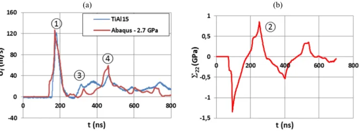
Figure 12a, for a =3.2 GW/cm² (0=2.7 GPa). The first velocity peak exhibits a 128 m/s amplitude (point
1), and is followed by reflected peaks (points 3 and 4). Abaqus reproduced rather well those first three peaks of the velocity profile, and allowed us determining numerically the interfacial stress profile (
Figure 12b): this indicated that a 0.81 GPa maximum uniaxial tensile stress was applied near the Ti /Al interface during the laser-shock loading.
Using the same procedure for increasing applied pressures, we could determine the bond strength of T40/A5754 joints.
This bond strength was estimated to 22th = 0.68 GPa (Figure 13), which can be considered as a relatively
high value for a metal-metal bond strength, especially compared with the tensile strength of assemblies (0.12 GPa in section 2.2). However, it has to be reminded that laser-shock waves generate ultra-high dynamic deformation (106 s-1) that tend to increase adhesion values compared with a quasi-static loading (scratch tests, interfacial indentation).
(a) (b)
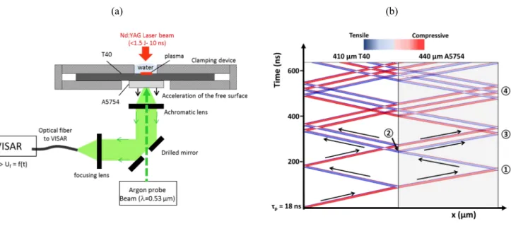
Figure 11: (a) Experimental detail of the LASAT bond test with VISAR, (b) (x,t) diagram of a (410 µm T40 + 440 µm A5754 system) impacted by a p=18 ns pressure pulse (≈ 9-10 ns laser pulse): a high amplitude tensile state is generated
at the interface after 230 ns (point 2), by the crossing of incident and reflected waves.
(a) (b)
Figure 12: (a) Experimental VISAR free velocity profile behind a (410 µm T40 + 440 µm A5754 system) impacted by a =3.2 GW/cm² laser pulse on a 1.5 mm diameter, and corresponding Abaqus simulation (estimated 0 = 2.7 GPa)
points 1, 3 and 4 are those shown in
Figure 11b, (b) Uniaxial interfacial stress 22 =f(t) profile calculated with Abaqus: a maximum 22 =0.81 GPa value is
obtained.
Figure 13: Experimental determination with VISAR of T40/A5754 bond strength. Each spot corresponds to the calculated 22 value of an experimental VISAR experiment. Above 22 = 0.68 GPa, corresponding to a maximum
applied pressure of approximately 0=2.2 GPa on the front T40 face, a reduction of the maximum velocity Uf (m/s) is
systematically observed on VISAR signals.
On the one hand, the potential of the LASAT technique for analyzing dissimilar joints was shown. On the other hand, the post-mortem analysis of cross-sections did not evidence macroscopic cracking near the interface, which seems to indicate that a local fracture occurred, clearly detected by VISAR, but that no full de-bonding could be generated at the Ti/Al interface. This may be due to the limited diameter (1.5 mm) of laser shock loading, and the limited mechanical impulse that was not sufficiently high to fracture entirely the interface. For this reason, future work should use higher energy lasers to provide larger spots (up to 5-6 mm in diameter), and higher mechanical impulses.
In this paper we considered the dissimilar laser joining of A5754 aluminum alloy with T40 titanium in lap joint condition. A brief process optimization was carried out that conduced us to use: (1) fluxing for favoring aluminum spreading and wetting on T40, and (2) black paint for enhancing laser absorptivity A (estimated to be near 0.4 after painting) and improving the global process efficiency. Microstructural and mechanical behavior of the assemblies carried out with or without filler wire were analyzed, and concluded to a limited depletion of Mg in fusion zones (FZ) assumed to be due to vaporization, and to rather sound and resistant TiAl3 interface layers. The maximum resistances, obtained during tensile
testing, were shown to be close to 300 N/mm, with fractures mostly occurring in the FZ, just above the intermetallic (IM) layer.
In a second step, specific T40/A5754 joints were performed, in terms of the fusion and spreading of a 3 mm –diameter 5754 cylinder on a T40 sheet, followed by polishing to ensure planar and parallel faces. This allowed us applying for the very first time the LASAT bond test to a dissimilar weld. Combining VISAR velocity measurements to numerical simulations, we could estimate an interfacial resistance (adhesion strength) of 0.68 GPa for a T40/A5754 joint bonded by a 2 µm-thick TiAl3 layer. The only
questionable point is that we could not identify precisely cracks coming from the LASAT test on post-mortem metallurgical cross-sections. This was ascribed to various potential factors such as: (1) the limited diameter of tensile zone at the interface (approximately 0.5 mm) that makes difficult the identification of cracks, (2) possible closure effects during shock waves propagation. For the very future, the LASAT technique seems to offer attractive aspects for testing dissimilar joints, especially by using larger spot diameters (> 5 mm) easily achievable by new generations of lasers. This should allow obtaining more macroscopic interfacial de-bonding for validating velocity measurements.
References
L. Berthe, R. Fabbro, P. Peyre, L. Tollier et E. Bartnicki , Shock waves from a water-confined laser-generated plasma, Journal of Applied Physics. 82 (6), 15 Sept 1997
L. Berthe, M. Arrigoni, M. Boustie, JP. Cuq-Lelandais, State-of-the-art of laser adhesion test LASAT bond test, Non-destructive Testing and Evaluation. 26 (2011), 303
Y. C. Chen, K. Nakata, Microstructural characterization and mechanical properties in friction stir welding of aluminum and titanium dissimilar joints, Materials and Design, 30 (2009-1), 469-474
Y. Chen, S. Chen, L. Li, Effects of heat input on microstructural and mechanical property of Al/Ti joints by rectangular spot laser welding-brazing method, International Journal of Manufacturing Technologies, 44 (2009-2), 265-272
S. Chen, L. Li, Y. Chen, J. Dai, J. Huang, Improving interfacial reaction non-homogeneity during laser welding-brazing aluminum to titanium, Materials and Design 32 (2011) 4408-4416
M. Dal, P.Peyre, Numerical calculation of Ti-Al assembly, ICALEO’13 Conference (Miami, USA), (2013)
S. P. Gupta, Intermetallic compounds in diffusion couples of Ti with an Al-Si eutectic alloy, Materials
Characterization, 49 (2003), 321-330
N. Kahraman, B. Gulenc, F. Findik, Corrosion and mechanical-microstructural aspects of dissimilar joints of Ti-6Al-4V and Al plates, International Journal of Impact Engineering, 34 (2007), 1423-1432
M. Kreimeyer, F. Wagner, F. Vollertsen, Laser processing of aluminum-titanium tailored blanks, Optics
and Lasers in Engineering 43(2005), 1021-1035
J. Liao, N. Yamamoto, H. Liu, K. Nakata, Microstructure at friction stir lap joint interface of pure titanium and steel, Materials Letters, 64 (2010), 2317-2320
Z. Ma, C. Wang, H. Yu, J. Yan, H. Shen, The microstructure and mechanical properties of fluxless gas tungsten arc welding-brazing made between titanium and aluminum alloys, Materials and Design, 45 (2013), 72-79
P. Peyre, G. Sierra, F. Deschaux-Beaume, D. Stuart, G. Fras, Generation of aluminium-steel joints with laser-induced reactive wetting, Materials Science & Engineering A, 444 (1-2) (2007), 327-338
P. Peyre, L. Berthe, V. Vignal, I. Popa and T. Baudin, Analysis of laser shock waves and resulting surface deformations in an Al-Cu-Li aluminium alloy, J.Phys.D : Appl.Phys, 45 (2012)
Z. Song, K. Nakata, A. Wu, J. Liao, Interfacial microstructure and mechanical property of Ti6Al4V/A6061 dissimilar joint by direct laser brazing without filler metal and groove, Materials Science
& Engineering A, 560 (2013), 111-120
W. V. Vaidya, M. Horstmann, V. Ventzke, B. Petrovski, M. Koçak, G. Tempus, Improving interfacial properties of a laser beam welded dissimilar joint of aluminum AA6056 and titanium Ti6Al4V for aeronautical applications, Journal of Materials Science, 45 (2010), 6242-6254
Acknowledgements: This work was supported by the French CARNOT program in the frame of the ATILA project. Authors would also like to thank Jindarat Kasemsooksakul, master student at ENSAM for helpful participation to the work.