Ultra-wideband Indoor Communications Using
Optical Technology
Th`ese pr´esent´ee `
a la Facult´e des ´etudes sup´erieures et postdoctorales de l’Universit´e Laval dans le cadre du programme de doctorat en g´enie ´electrique
pour l’obtention du grade de Philosophiæ Doctor (Ph.D.)
Facult´e des sciences et de g´enie UNIVERSIT´E LAVAL
QU´EBEC
2013
c
La communication ultra large bande (UWB) a attiré une énorme quantité de recherches ces dernières années, surtout après la présentation du masque spectral de US Federal Communications Commission (FCC). Les impulsions ultra-courtes permettent de très hauts débits de faible puissance tout en éliminant les interférences avec les systèmes existants à bande étroite. La faible puissance, cependant, limite la portée de propaga-tion des radios UWB à quelques mètres pour la transmission sans fil à l’intérieur d’une pièce. En outre, des signaux UWB reçu sont étendus dans le temps en raison de la propagation par trajet multiple qui résulte en beaucoup d’interférence inter-symbole (ISI) à haut débit.
Le monocycle Gaussien, l’impulsion la plus commune dans UWB, a une mauvaise couverture sous le masque de la FCC. Dans cette thèse, nous démontrons des transmet-teurs qui sont capables de générer des impulsions UWB avec une efficacité de puissance élevée. Une impulsion efficace résulte dans un rapport de signal à bruit (SNR) supérieur au récepteur en utilisant plus de la puissance disponible sous le masque spectral de la FCC. On produit les impulsions dans le domaine optique et utilise la fibre optique pour les transporter sur plusieurs kilomètres pour la distribution dans un réseau optique pas-sif. La fibre optique est très fiable pour le transport des signaux radio avec une faible consommation de puissance. On utilise les éléments simples comme un modulateur Mach-Zehnder ou un résonateur en anneau pour générer des impulsions, ce qui permet l’intégration dans le silicium. Compatible avec la technologie CMOS, la photonique sur silicium a un potentiel énorme pour abaisser le coût et l’encombrement des systèmes optiques. La photodétection convertit les impulsions optiques en impulsions électriques avant la transmission sur l’antenne du côté de l’utilisateur.
Nous proposons une technique d’optimisation non-linéaire qui prend en compte la dis-torsion d’antenne pour trouver des impulsions qui maximisent la puissance transmise, en respectant le masque spectral de la FCC. Nous travaillons avec trois antennes et con-cevons une impulsion unique pour chacune d’entre elle. L’amélioration de l’énergie des impulsions UWB améliore directement la SNR au récepteur. Les résultats de simulation montrent que les impulsions optimisées améliorent considérablement le taux d’erreur (BER) par rapport au monocycle Gaussien sous propagation par trajet multiple.
Notre autre contribution est l’évaluation d’un filtre adapté pour recevoir efficace-ment des impulsions UWB. Le filtre adapté est synthétisé et fabriqué en technologie microstrip, en collaboration avec l’Université McGill comme un dispositif de bande interdite électromagnétique. La réponse fréquentielle du filtre adapté montre une ex-cellente concordance avec le spectre ciblé de l’impulsion UWB. Les mesures de BER confirment la performance supérieure du filtre adapté par rapport à un récepteur à conversion directe.
Le canal UWB est très riche en trajet multiple conduisant à l’ISI à haut débit. Notre dernière contribution est l’étude de performance des récepteurs en simulant un système avec des conditions de canaux réalistes. Les résultats de la simulation montrent que la performance d’un tel système se dégrade de façon significative pour les hauts débits. Afin de compenser la forte ISI dans les taux de transfert de données en Gb/s, nous étudions l’algorithme de Viterbi (VA) avec un nombre limité d’états et un égaliseur DFE (decision feedback equalizer). Nous examinons le nombre d’états requis dans le VA, et le nombre de coefficients du filtre dans le DFE pour une transmission fiable de UWB en Gb/s dans les canaux en ligne de vue. L’évaluation par simulation de BER confirme que l’égalisation améliore considérablement les performances par rapport à la détection de symbole. La DFE a une meilleure performance par rapport à la VA en utilisant une complexité comparable. La DFE peut couvrir une plus grande mémoire de canal avec un niveau de complexité relativement réduit.
Ultra-wideband (UWB) communication has attracted an enormous amount of research in recent years, especially after the introduction of the US Federal Communications Commission (FCC) spectral mask. Ultra-short pulses allow for very high bit-rates while low power eliminates interference with existing narrowband systems. Low power, however, limits the propagation range of UWB radios to a few meters for indoors wireless transmission. Furthermore, received UWB signals are spread in time because of multipath propagation which results in high intersymbol interference at high data rates.
Gaussian monocycle, the most commonly employed UWB pulse, has poor coverage under the FCC mask. In this thesis we demonstrate transmitters capable of generating UWB pulses with high power efficiency at Gb/s bit-rates. An efficient pulse results in higher signal-to-noise ratio (SNR) at the receiver by utilizing most of the available power under the FCC spectral mask. We generate the pulses in the optical domain and use optical fiber to transport the pulses over several kilometers for distribution in a passive optical network. Optical fiber is very reliable for transporting radio signals with low power consumption. We use simple elements such as a Mach Zehnder modulator or a ring resonator for pulse shaping, allowing for integration in silicon. Being compatible with CMOS technology, silicon photonics has huge potential for lowering the cost and bulkiness of optical systems. Photodetection converts the pulses to the electrical domain before antenna transmission at the user side.
The frequency response of UWB antennas distorts the UWB waveforms. We pro-pose a nonlinear optimization technique which takes into account antenna distortion to find pulses that maximize the transmitted power, while respecting the FCC spectral mask. We consider three antennas and design a unique pulse for each. The energy
im-provement in UWB pulses directly improves the receiver SNR. Simulation results show that optimized pulses have a significant bit error rate (BER) performance improvement compared to the Gaussian monocycle under multipath propagation.
Our other contribution is evaluating a matched filter to receive efficiently designed UWB pulses. The matched filter is synthesized and fabricated in microstrip technology in collaboration with McGill University as an electromagnetic bandgap device. The frequency response of the matched filter shows close agreement with the target UWB pulse spectrum. BER measurements confirm superior performance of the matched filter compared to a direct conversion receiver.
The UWB channel is very rich in multipath leading to ISI at high bit rates. Our last contribution is investigating the performance of receivers by simulating a system employing realistic channel conditions. Simulation results show that the performance of such system degrades significantly for high data rates. To compensate the severe ISI at gigabit rates, we investigate the Viterbi algorithm (VA) with a limited number of states and the decision feedback equalizer (DFE). We examine the required number of states in the VA, and the number of taps in the DFE for reliable Gb/s UWB trans-mission for line-of-sight channels. Non-line-of-sight channels were also investigated at lower speeds. BER simulations confirm that equalization considerably improves the performance compared to symbol detection. The DFE results in better performance compared to the VA when using comparable complexity as the DFE can cover greater channel memory with a relatively low complexity level.
R´esum´e iii
Abstract v
Contents vii
Acknowledgements x
List of Figures xi
List of Tables xvi
Acronyms and Abbreviations xvii
1 Introduction 1
1.1 Motivation . . . 1
1.2 Objectives and Major Contributions . . . 3
1.3 Structure of the thesis . . . 4
2 UWB communication systems 6 2.1 UWB basics . . . 6
2.1.1 UWB applications . . . 9
2.1.2 Impulse radio vs. multiband UWB . . . 10
2.2 UWB pulse generation techniques . . . 11
2.2.1 Pulse generation in the electrical domain . . . 12
2.2.2 Pulse generation in the optical domain . . . 14
2.3 UWB channel models and measurements . . . 18
2.3.1 Path loss model . . . 18
2.3.2 Multipath model . . . 19
2.4 UWB antennas . . . 20
2.5.1 Coherent UWB receivers . . . 22
2.5.2 Noncoherent UWB receivers . . . 23
2.6 Conclusion . . . 26
3 UWB Pulse generation techniques 28 3.1 EIRP calculation method . . . 29
3.2 Upconversion of Gain-Switched Laser Pulses for Generation of UWB Signals . . . 33
3.2.1 Introduction . . . 33
3.2.2 Experimental setup . . . 35
3.2.3 Simulation and Experimental Results . . . 38
3.2.4 BER performance of the receiver . . . 43
3.3 Low Complexity generation of BPSK UWB signals . . . 47
3.3.1 Introduction . . . 47
3.3.2 Experimental Setup . . . 49
3.3.3 Theoretical Study . . . 50
3.3.4 Experimental Results and Discussion . . . 51
3.4 UWB waveform generation using a microring resonator . . . 56
3.4.1 Introduction . . . 56
3.4.2 Principle of Operation and RTR design . . . 60
3.4.3 Experimental Results and Discussion . . . 66
3.5 Conclusion . . . 67
4 UWB pulse shaping: bypassing the limitations of the monocycle 70 4.1 UWB Pulse Design . . . 72
4.2 Common UWB pulse shapes . . . 73
4.3 Antennas and Efficient UWB Pulses . . . 74
4.3.1 The SkyCross Antenna . . . 75
4.3.2 The circular monopole antenna . . . 76
4.3.3 The monopole antenna with two steps . . . 78
4.4 Experimental Validation . . . 78
4.4.1 Pulse Generation . . . 78
4.4.2 Pulse characterization . . . 80
4.5 Simulation Results and Discussion . . . 81
4.6 Conclusion . . . 85
5.1 UWB Reception Using an EBG . . . 87
5.1.1 Introduction . . . 87
5.1.2 Experimental setup . . . 88
5.1.3 EBG Design and Fabrication . . . 90
5.1.4 Matched filter characterization . . . 91
5.1.5 BER measurement and discussion . . . 93
5.2 Equalizers for IR-UWB Linear Receivers . . . 95
5.2.1 System Model . . . 97
5.2.2 Equalization . . . 99
5.2.3 Simulation results . . . 101
5.3 Conclusion . . . 105
6 Conclusions and Future Work 107
Publication List 110
There are many people who have helped me throughout the course of my graduate study. I would like to thank my advisor professor Leslie A. Rusch, for her guidance, encouragement and support throughout my graduate career. We have had regular discussions over the last six years. The opportunities for growth and the excitement of working in our group are deeply appreciated; I am honored to have had the chance to be part of it. My gratitude also goes to professor Sophie LaRochelle who was my M.Sc. cosupervisor and has continued to be a great inspiration for the work in this thesis. We held many meetings with professor LaRochelle to discuss optical aspects of this work.
I thank the members of the jury Prof. Jianping Yao, Prof. José Aza˜na, and Prof. Jean-Yves Chouinard for taking the time to read my thesis. I would also like to thank members of my pre-doctoral exam Prof. Tayeb Denidni and Prof. David Plant for their time and many fruitful comments about the project.
Several members of Leslie and Sophie group have contributed to this work and others have been good friends. I want to particularly thank David, Amir, Mehdi, Francesco, Ramtin, Alexandre, and Mansour. Being in COPL with you all has been a pleasure. Greatest thanks to Dr. Mohammad Abtahi without whom this project would have never started. He was always there with motivating discussions, and shared with me his technical experience. I would like to thank the COPL technicians Philippe Chrétien and Patrick LaRochelle for their help in experiments. Dr. Joshua Schwartz designed and fabricated the EBGs, many thanks to him for all the discussions we had. I am also grateful to Prof. Lukas Chrostowski for teaching me about silicon photonics and to Dan Deptuck for his help with chip layout.
My deepest appreciation goes to my parents Afsaneh and Ali for their support and kindness. They have always been there for me, provided me with the best education and encouraged me to learn. My brothers Farshad and Farzad and my final gratitude to my grandmother Afsar who has always encouraged me to become a scientist.
1.1 FCC spectral masks for indoor and outdoor communication applications [1]. 2
2.1 WiMedia landscape of UWB compared to Wireless local area networks (WLAN) [2] . . . 8
2.2 (a) impulse radio (IR-UWB), and (b) multiband (MB-UWB). . . 11
2.3 UWB pulse generation techniques. (a) upconversion of baseband pulses, (b) shaping baseband pulses using a filter, (c) optical generation/transport of UWB signals, and (d) electrical UWB pulse generation. . . 12
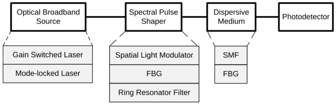
2.4 Schematic diagram of pulse generation by spectral pulse shaping. SMF: single-mode fiber, FBG: fiber Bragg grating. . . 14
2.5 Block diagram of the UWB waveform generator. . . 16
2.6 A WDM-PON network transporting UWB radio signals. . . 17
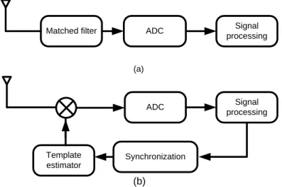
2.7 Coherent receivers: The matched filter receiver (a), and the correlation receiver (b). ADC: analog-to-digital convertor. . . 22
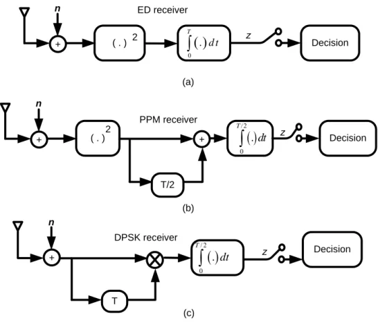
2.8 Generic noncoherent UWB receiver structures: the energy detection (ED) for OOK receiver(a), the ED receiver for PPM modulation, and the DPSK noncoherent receiver. . . 25
3.1 (a) The experimental setup for measuring the antenna frequency re-sponse,(b) antenna frequency response, (c) antenna link delay, and (d) antenna reflection response. . . 30
3.2 (a) Smoothed antennas frequency response, (b) normalized time response. 32
3.3 PA frequency response. . . 32
3.4 Simplified block diagram of the proposed UWB waveform generator. GSL: gain switched laser, FBG: fiber Bragg grating, SMF: single-mode fiber. . . 33
3.5 The schematic diagram of the proposed UWB waveform generator, and the receiving schemes. GSL: gain-switched laser, PC: polarization con-troller, MZM: Mach-Zehnder modulator, SMF: single-mode fiber, FBG: fiber Bragg grating, EDFA: erbium-doped fiber amplifier, BPF: bandpass filter, VOA: variable optical attenuator, DL: delay line, ATT: attenuator, BPD: balanced photodetector, LNA:low-noise amplifier. . . 35
3.6 The simulated and measured response of the FBG at transmission and reflection. . . 37
3.7 (a) the simulated and measured response at the MZM output (from the positive input of the BPD), and the measured GSL pulse after 20 km fiber propagation (from the negative input of the BPD). (b) the simulated and measured UWB waveforms. (c) The normalized PSD and EIRP of the UWB pulse. . . 40
3.8 The normalized PSD of UWB waveforms for various optical fiber lengths plotted against the 3.1-10.6 GHz band of the FCC spectral mask. . . . 41
3.9 (a) UWB waveform generated using the FBG filter at the transmitter, (b) The normalized PSD and EIRP of the UWB pulse. . . 42
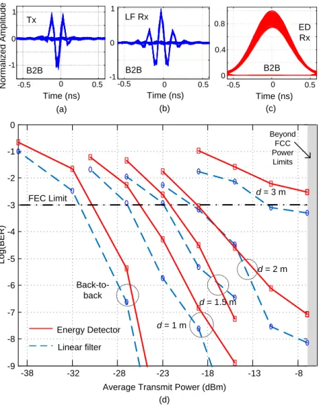
3.10 UWB transmitter with 20 km of SMF, (a) ayediagram of the transmit pulse, (b) eyediagram of the linear filter output, (c) eyediagram of the energy detector output, (d) BER versus average transmit power plotted for various wireless distances. . . 44
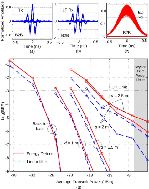
3.11 UWB transmitter with FBG filter, (a) eyediagram of the transmit pulse, (b) eyediagram of the linear filter output, (c) eyediagram of the energy detector output, (d) BER versus average transmit power plotted for var-ious wireless distances. . . 46
3.12 (a) BER versus wireless transmission distance. The average transmit power is set to -6.5 dBm for the transmitter with the FBG filter. . . 47
3.13 The schematic diagram of the experimental setup. PC: polarization controller, MZM: Mach-Zehnder modulator, VOA: variable optical at-tenuator, SMF: single-mode fiber, PD: photodetector, LNA: low-noise amplifier, LPF: lowpass filter. . . 49
3.14 (a) The normalized transmit UWB signal, (b) the normalized received waveform, and (c) the power spectral density of the transmit pulse (red) and the EIRP (blue). . . 52
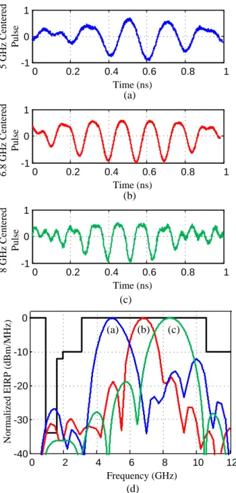
3.15 The multiband-UWB signals centered around (a) 5 GHz, (b) 6.8 GHz, and (c) 8.5 GHz. (d) The corresponding EIRP plots. . . 53
3.16 The PSK scheme. (a) The transmit UWB pulses, (b) the received wave-forms, (c) the autocorrelation function of the received waveform, (d) superposition of a 1 and a 0, and (e) the EIRP of the 1 and 0 pulses. . 55
3.17 The PSK signals. (a) The eyediagram of the UWB signal at the trans-mitter, (b) The eyediagram of the received signal after 50 cm of wire-less propagation, (c) the power spectral density of the transmit pulses obtained from the electrical spectrum analyzer (gray), the normalized EIRP (blue), vs. the FCC mask (red). (d) the BER performance for back-to-back and 20 km SMF. . . 57
3.18 BER performance of the receiver with no equalization (solid blue), and with MMSE equalizer (dashed red) are compared for several wireless distances. . . 58
3.19 The schematic diagram of the experimental setup. Gain-switched laser: GSL, SMF: single-mode fiber, polarization controller: PC, erbium-doped fiber amplifier: EDFA, bandpass filter: BPF, photodetector: PD. . . . 60
3.20 Y-splitter. (a) Lumerical layout (b) power versus position, blue curve is at the input and the green is at the output. . . 61
3.21 The amplitude of the electric field. (a) symmetric supermode, and (b) the anti-symmetric supermode. . . 62
3.22 (a) the effective indices of the symmetric and antisymmetric supermodes, and (b) the difference of the two indices. . . 63
3.23 Simulation result for filtering the gain-switched laser with the RTR notch filter. . . 65
3.24 The design layout from DW-2000 software. . . 65
3.25 (a) picture of the fabricated chip; the portion dedicated to our design is indicated by a red box, (b) a scanning electron microscope (SEM) image of an RTR, and (c) the SEM image of the Y-splitter. . . 66
3.26 Simulated (dotted blue) and measured (solid red) transmission response of the RTR. . . 67
3.27 The generated UWB waveforms. (a) The time domain waveforms for the filtered and unfiltered branches, and the resulting UWB pulse. (b) The PSD and the calculated EIRP of the UWB pulse. Simulation results match the experiment. . . 68
4.1 Commonly used UWB pulses. (a) the Gaussian 5th derivative, (b) the Gaussian monocycle, (c) a highpass filtered gaussian monocycle pulse, and (d) the corresponding spectra with respect to the normalized FCC spectral mask. . . 74
4.2 (a) The SkyCross antenna structure, (b) the measured channel frequency response, (c) the effective mask (dotted, green), the normalized EIRP-optimized pulse spectral density (target in dashed red, and measured in solid blue), and (d) the normalized EIRP-optimized pulses in the time domain (target in dashed red, and measured in solid blue). . . 76
4.3 (a) the circular monopole antenna, (b) the measured channel frequency response, (c) the effective mask (dotted, green), the normalized EIRP-optimized pulse spectral density (target in dashed red, and measured in solid blue), and (d) the normalized EIRP-optimized pulses in the time domain (target in dashed red, and measured in solid blue). . . 77
4.4 (a) the monopole antenna with two steps, (b) the measured channel fre-quency response, (c) the effective mask (dotted, green), the normalized EIRP-optimized pulse spectral density (target in dashed red, and mea-sured in solid blue), and (d) the normalized EIRP-optimized pulses in the time domain (target in dashed red, and measured in solid blue). . . 79
4.5 The schematic diagram of the arbitrary UWB waveform generator. GSL: gain switched laser, SMF: Single mode fiber, BPD: balanced photodetec-tor, FBG: fiber Bragg grating, HE: Heating element, [3]. . . 80
4.6 The EIRP-optimized pulse (solid, blue) and the Gaussian 5thorder deriva-tive (dotted, red) (3), and the Gaussian monocycle pulse (dashed, green); for (a) the SkyCross, (b) the circular monopole, and (c) the monopole antenna with two steps. . . 81
4.7 BER simulations; (a) the AWGN channel, (b) average over 52 LOS indoor multipath UWB channels. . . 84
5.1 (a) The target UWB waveform (dotted line) and the generated pulse (solid line), (b) The spectral density of the generated UWB waveform under the FCC mask. . . 89
5.2 The schematic diagram of the UWB transmitter and receiver systems. GSL: gain switched laser, PC: polarization controller, MZM: Mach-Zehnder modulator, DL: delay line, ATT: attenuator, PD: photodetector, EBG: electromagnetic bandgap, LO: local oscillator, BERT: bit-error-rate tester. 90
5.3 Characterization of the EBG filter. (a) The target frequency response of the filter, the measured response, and the response of the filter when used with the circulator, (b) the impulse response of the EBG compared to the ideal matched filter impulse response. Amplitude values are normalized. 91
5.4 The normalized output waveform of the matched filter. The measure-ment is in good agreemeasure-ment with the theory. . . 92
5.5 (a) The output waveform of the matched filter for a bit sequence of [1 0 0 1 1 1 0 0 1], (b) the output of the direct conversion receiver for the same bit sequence. . . 94
5.6 The measured BER curves for the matched filter and the direct conver-sion receivers. . . 94
5.7 (a) LOS impulse response measurement (b) NLOS impulse response mea-surement. . . 96
5.8 The system model. . . 98
5.9 BER simulations of OOK UWB signals in LOS multipath channel con-ditions; (a) symbol detection, and (b) the VA versus the DFE. . . 102
5.10 BER simulations of BPSK UWB signals in LOS multipath channel con-ditions; (a) symbol detection, and (b) the VA versus the DFE. . . 104
5.11 BER simulations of BPSK UWB signals in NLOS multipath channel conditions. . . 105
5.12 The fault percentage of NLOS UWB signal detection using a DFE with 21 taps. . . 106
3.1 Link budget . . . 43
3.2 Design Parameters . . . 64
4.1 Relative power efficiency of antennas under study; Ant. 1: the SkyCross, Ant. 2: the circular monopole, and Ant. 3: the monopole antenna with two steps. . . 82
ADC Analog-to-digital convertor . . . .22
ASE amplified spontaneous emission . . . .36
AT T attenuator . . . .15
AW GN additive white Gaussian noise . . . .24
BER Bit-error-rate . . . .4
BP D balanced photodetector . . . .15
BP F bandpass filter . . . .38
BP SK binary Phase shift-keying . . . .3
CF BG chirped fiber Bragg grating . . . .79
CM OS Complementary metalŰoxideŰsemiconductor . . . .13
CW continuous wave . . . .35
DF B distributed feedback . . . .35
DF E decision feedback equalizer . . . .4
DL delay line . . . .15
DP SK differential PSK . . . .24
E/O electrical to optical conversion . . . .13
EBG electromagnetic bandgap . . . .88
ED energy detector . . . .23
EIRP equivalent isotropically radiated power . . . .1
F BG fiber Bragg grating . . . .2
F CC Federal Communications Commission . . . .1
F EC forward error correction . . . .34
F IR finite impulse response . . . .72
F SR free spectral range . . . .66
F W HM full-width half-maximum . . . .35
GA genetic algorithm . . . .73
GSL gain-switched laser . . . .16
GV D group velocity dispersion . . . .64
HDT V high definition television . . . .1
HE heating element . . . .79
HP F highpass filter . . . .70
IR − U W B impulse radio UWB . . . .10
ISI intersymbol interference . . . .18
LAN local area network . . . .1
LN A low-noise amplifier . . . .8
LO local oscillator . . . .12
LOS line-of-sight . . . .18
LP F lowpass filter . . . .51
M B − U W B multiband UWB . . . .10
M LSE maximum likelihood sequence estimator . . . .100
M M SE minimum-mean-square-error. . . .48
M ZM Mach-Zehnder modulator . . . .34
N F noise figure . . . .43
N LOS non-line-of-sight . . . .18
N RZ non-return-to-zero . . . .55
OF DM orthogonal frequency-division multiplexing. . . .34
OOK on-off keying . . . .9
P A power amplifier . . . .31
P AM pulse amplitude modulation . . . .9
P C polarization controller . . . 36
P CB Printed circuit board . . . .21
P E power efficiency . . . .41
P LL phase-locked-loop . . . .37
P ON passive optical network . . . .3
P P M pulse position modulation . . . .9
P RBS pseudorandom bit sequence . . . .43
P SD power spectral density . . . .36
QAM quadrature amplitude modulation . . . .109
QP SK quadrature Phase Shift Keying . . . .109
RF radio frequency . . . .3
RF radio frequency . . . .17
RM S root mean square . . . .19
RT R race-track ring resonator . . . .58
Rx receiver . . . .30
SM F single mode fiber . . . .14
SN R signal-to-noise ratio . . . .2
SOI silicon-on-insulator . . . .58
SQP sequential quadratic program . . . .71
T DM A time-division multiple access . . . .16
T R transmitted reference . . . .24
T x transmitter . . . .30
U M T S universal mobile telecommunication system . . . .7
U V ultraviolet . . . .36
U W B ultra-wideband . . . .1
V A Viterbi algorithm . . . .4
V N A vector network analyzer . . . .31
V OA variable optical attenuator . . . .50
W DM wavelength-division-multiplexed . . . .3
Introduction
1.1
Motivation
Today, wireless communications is the fastest growing segment of the communication industry. Cellular phones and the Internet have rapidly become an essential part of our everyday life. The popularity of streaming videos over the Internet has caused a growth in bandwidth demand. Nowadays, the popularity of high definition television (HDTV) is particularly pushing up bandwidth demand. The Internet is typically brought to homes by cables with migration to optical fiber considered for the future. Once in the home, people seek the convenience of wireless access. There are usually other personal devices at home, such as printers, cameras, and DVD players. The communication between the computer and these devices is primarily accomplished by cable connections. Wouldn’t it be amazing to connect all these devices with no cable at all?
The IEEE 802.11 wireless LAN data rates are not high enough for the mentioned applications. Ultra-wideband (UWB) communications is a research field that promises very high data rate wireless indoor communications. To support deployment of UWB radio, the US Federal Communications Commission (FCC) issued its first report in 2002 [1]. Per this ruling, UWB radio enjoys a huge 7.5 GHz bandwidth, from 3.1 GHz to 10.6 GHz. However, the equivalent isotropically radiated power (EIRP) from a UWB device should be below a spectral mask (Figure 1.1). The radiated power constraints ensure UWB systems do not cause interference with other coexisting narrowband systems. Power limitations make UWB radio short range. Currently, UWB systems have a
EIRP transmissio n level (dBm/MHz) 0 4 8 12 Frequency (GHZ) -41.3 7.5 GHz 3.1 GHz 10.6 GHz -51.3 -75.3 -51.3
Figure 1.1: FCC spectral masks for indoor and outdoor communication applications [1]. range of a few meters and are limited within a room. This is a major drawback for practical applications of UWB.
To extend the range of UWB communications, pulse shaping techniques that use most of the available power under the FCC spectral mask are essential. Furthermore, fiber transport of UWB signals extend their reach from a few meters to several kilo-meters. Direct generation of UWB signals in the optical domain attracted a growing interest in recent years [5–11].
At Laval University, we have previously developed an optical pulse shaping method to precisely generate very efficient UWB pulses that closely respect the FCC spectral mask [11]. Our pulse shaping method is based on spectral shaping of a laser source using a fiber Bragg grating (FBG) .
Although optics is a favorable environment for transport of UWB signals, the ul-timate goal is wireless transmission and error free reception. Highly efficient pulses result in a better signal-to-noise ratio (SNR) at the receiver. Better SNR will reduce errors and extend the reach for indoor communication purposes. Nevertheless, an ef-ficient pulse shape does not guarantee the quality of the communication as there are many more challenges to the system. The wireless channel, for example, significantly affects the received signal. Realistic propagation scenarios need to be chosen to cor-rectly model the received signals. The channel information will help us in choosing appropriate transmitter and receiver structures.
1.2
Objectives and Major Contributions
We propose three optical solutions for low cost generation of UWB signals. Our so-lutions are compatible with wavelength-division-multiplexed passive optical network (WDM-PON) distribution. We provide detailed simulation and experimental results of the optical pulse generators, as well as wireless transmission and receiver error per-formance analysis. We select pulse shaping components that promise future optical on-chip UWB transmitters.
Our first approach is based on using a Mach-Zehnder modulator to upconvert on-off keying (OOK) baseband pulses to the center of the FCC spectral mask. The optical pulses are produced by a gain switched laser. We show good power efficiencies for fiber distances between 15 km and 25 km. The optical fiber can be replaced by an FBG filter to make a compact optical UWB transmitter for applications that do not require fiber, i.e., not PON.
A continuous wave laser, a Mach-Zehnder modulator, and a photodetector are the only optical components we use in our second pulse generator. A combination of data and a sinusoidal signal are used to generate binary phase shift-keying (BPSK) UWB signals at 1.75 Gb/s. BPSK has a lower error rate at a given SNR compared to other binary digital modulation formats.
In the third case, we propose an integrated pulse generation solution; gain-switched laser pulses are spectrally filtered by a silicon micro-ring resonator. Single mode fiber propagation performs the frequency-to-time mapping and balanced photodetection re-moves the low frequency components of the generated RF signals. OOK UWB pulses generated by this method show good power efficiency.
Many possible transmitter and receiver structures exist, motivating us to develop a MATLAB simulator to investigate the performance of candidate solutions. The sim-ulator uses multipath channels measured by Intel Corporation [4]. By exploiting the properties of the channel, it is possible to design receiver algorithms that achieve good performance. Our simulations investigate the significance of pulse shaping in improve-ment of bit error rate under multipath interference. We simulate a linear filter matched to the transmit waveform and also an energy detector.
In order to highlight the effect of pulse shaping and show the capability of our tech-nique under different channel circumstances, we test the system with different UWB antennas. We seek antennas that not only function over the whole UWB bandwidth, but also show high omni-directionality in all the bandwidth. After fabrication of the an-tennas and designing the corresponding efficient pulses, the versatility of our technique is investigated experimentally.
To compensate the severe intersymbol interference at gigabit rates, we investigate the Viterbi algorithm (VA) with a limited number of states and the decision feedback equalizer (DFE). We examine the required number of states in the VA, and the number of taps in the DFE for reliable Gb/s UWB transmission for Intel channels. Bit-error-rate (BER) simulations confirm that equalization considerably improves the performance compared to symbol detection.
Implementation of a matched filter is a challenging task in RF. We evaluate ex-perimentally a matched filter synthesized and fabricated in microstrip technology. We show that the output of the microstrip matched filter is close to an ideal matched filter response. BER simulations quantify the superior performance of the matched filter compared to a direct conversion receiver.
1.3
Structure of the thesis
Following the introduction in Chapter 1, which summarizes the motivation and the objectives of this research, Chapter2presents review of complete UWB systems. After some basic concepts about UWB communications, pulse shaping methods are discussed with emphasis on the optical domain techniques. We present UWB channel models and also briefly review UWB antenna properties. This chapter ends with a look at UWB receivers.
In Chapter 3 we present three optical UWB pulse generation methods. The first two methods use a Mach-Zehnder modulator to upconvert signals from baseband to the center of the FCC mask. The third method is an integrated solution based on a micro-ring filter in silicon.
anten-nas. We show the antenna impulse response can be used to improve the UWB pulse design. We simulate the effect of pulse shaping in multipath channels. BER curves are presented for various pulse shapes.
Equalization of UWB signals in multipath channel is discussed in Chapter 5. We compare the Viterbi algorithm with the decision feedback equalizer for a linear receiver. The linear receiver examined is fabricated as an electromagnetic bandgap structure. We characterize the linear filter and also compare its BER performance with a direct conversion receiver.
UWB communication systems
Connectivity for everyone and everything at any place and any time is the vision of wireless systems beyond the third generation. Short-range wireless technology will play a key role in scenarios of ubiquitous communications over different types of links [12]. Novel devices based on ultra-wideband radio technology have the potential to provide solutions for many of today’s problems in the area of spectrum management and radio system engineering.
This chapter is dedicated to a literature review of UWB systems. In section 2.1, basic UWB radio concepts are presented. Subsequently, in Section 2.2, we review UWB pulse shaping methods in both the electrical domain and in the optical domain, the latter in more detail. In Section 2.3, we present multipath channel models and channel measurements available for UWB. In Section 2.4, the main characteristics of UWB antennas are presented. Four UWB antenna designs are discussed in detail. In Section2.5, we investigate UWB receiver structures. Possible modulation schemes are presented for each structure.
2.1
UWB basics
UWB technology has existed since the 1980s. It mainly has been used for radar ap-plications because of the wideband nature of the signal that results in very accurate timing information. In the early days UWB was referred to as impulse radio, where
an extremely short pulse with no carrier was used instead of modulating a sinusoid to transmit information. These sub-nanosecond pulses occupy several GHz of bandwidth and are transmitted with very low duty cycles. In April 2002, the FCC issued its first report on UWB technology, thereby providing regulations to support deployment of UWB radio systems [1]. These regulations allowed the UWB radios to coexist with already allocated narrowband radio frequency (RF) emissions.
The band allocated to UWB communications is 7.5 GHz wide, by far the largest allocation of bandwidth to any commercial terrestrial system. The FCC UWB rul-ings allocated 1500 times the spectrum allocation of a single UMTS (universal mobile telecommunication system) license [13]. However, the available power levels are very low. If the entire 7.5 GHz band is optimally utilized, the maximum power available to a transmitter is approximately 0.5 mW. This effectively relegates UWB to indoor, short range, communications for high data rates, or very low data rates for substantial link distances. In principle, trading data rate for link distance can be as simple as increasing the number of pulses used to carry 1 bit. The more pulses per bit, the lower the data rate, and the greater the achievable transmission distance.
UWB devices are intentional radiators under FCC Part 15 Rules. For a radiator to be considered UWB the fractional bandwidth defined as
Bf = 2
fH − fL
fH + fL
(2.1) must be at least 0.2. In the formula above, fH and fL are the higher and lower -10 dB
frequencies, respectively. The radiation limits set by the FCC are presented in Figure
1.1 for indoor and outdoor data communication applications. These limitations are ex-pressed in terms of equivalent isotropically radiated power (EIRP). EIRP is the product of the transmit power from the antenna and the antenna gain in a given direction rela-tive to an isotropic antenna. Allowed UWB emission levels are less than or equal to the level allowed for unintentional radiators such as computers and other electronic devices (-41.3 dBm/MHz). Thus, UWB systems can coexist with other narrowband networks; the interference caused by a UWB transmitter can be viewed as a wideband interferer, and it has the effect of raising the noise floor of the narrowband receiver. A benefit to UWB of this low power constraint is preserving battery life. Another benefit of low power is low probability of detection which is a concern for both military and consumer applications. The weak UWB pulses are inherently short range which makes the op-eration of multiple independent links possible within the same house. The broadband property of the UWB signal makes it resistant to interference because any interfering
Figure 2.1: WiMedia landscape of UWB compared to Wireless local area networks (WLAN) [2]
signal is likely to affect a small portion of the desired signal spectrum.
UWB can provide very high speed but short distance communication links. Fig. 2.1
shows the WiMedia landscape of UWB services compared to IEEE 802.11 networks [2]. It can be seen that UWB is the fastest in close range while the IEEE 802.11 is more suitable for distances more than 10 m. The spatial capacity, an indicator of data intensity in a transmission medium, is over 106 bit
s.m2 for UWB. No current commercial system is capable of reaching a spatial capacity as high as that of a UWB system. This can be explained by the Shannon channel capacity theorem [14]. The upper bound on the capacity of a channel grows linearly with the available bandwidth. Thus, the UWB systems occupying several GHz of bandwidth show great potential for the future high capacity wireless networks.
Some important issues attributable to UWB are discussed here.
a) Antennas: Antennas have a filtering effect on the UWB pulse. Good impedance matching over the entire UWB bandwidth is desired to reduce reflection losses from the antennas. The impulse response of the antenna changes with angles in azimuth and elevation. Therefore, the transmitted pulse is differently distorted at every angle.
b) Low noise amplifiers (LNAs): Design of amplifiers is another challenge for UWB applications. Due to the low power and wideband nature of the UWB signal, very low noise and wideband amplifiers are essential at the receiver side.
c) Modulation: For pulsed UWB systems, the widely used modulation schemes are pulse amplitude modulation (PAM), on-off keying (OOK), and pulse position modula-tion (PPM). The OOK scheme results in energy detecmodula-tion receivers of lower complexity, whereas the PPM shows better error performance but lower bit rates.
d) Multipath: In the indoor environment the signal bounces off objects located be-tween the transmitter and receiver creating multipath reflections. If the delay spread of the echoes is smaller than the pulse width, the echoes can combine destructively leading to multipath fading. However, for an indoor UWB system with a range of 10 m, the delay spread is typically several nanoseconds, significantly more than a typical UWB signal pulse width. This makes UWB resistant to multipath interference. To maxi-mize the received energy, one can use a RAKE receiver to combine the signals coming over resolvable propagation paths. However, combining many multipath components increases the complexity of the receiver.
2.1.1
UWB applications
Among recent applications of UWB are the following.
1. Cable replacement: Today, most computer and consumer electronic devices (ev-erything from a digital camcorder and DVD player to a mobile PC and a high-definition TV (HDTV)) require wires to record, play or exchange data. UWB will eliminate these wires, allowing people to ”unwire” their lives in new and un-expected ways [15]. A mobile computer user could wirelessly connect to a digital projector in a conference room. Digital pictures could be transferred to a photo print kiosk for instant printing without the need of a cable. An office worker could put a mobile PC on a desk and instantly be connected to a printer or a scanner. 2. Wireless Personal Area Networking (WPAN): A high speed wireless UWB link can connect cell phones, laptops, cameras, MP3 players. This technology provides much higher data rates than Bluetooth or 802.11. With UWB a portable MP3 player could stream audio to high-quality surround-sound speakers anywhere in the room.
3. Vehicle collision avoidance: UWB can provide enough resolution to distinguish cars, people, and poles on or near the road. This information can be used to
alert the driver and prevent collisions. UWB radar has the resolution to sense road conditions (i.e., potholes, bumps, and gravel vs. pavement) and provide information to dynamically adjust suspension, braking, and other drive systems. 4. Radar: UWB can provide centimeter accuracy in ranging because of its high time resolution. Improved object identification (greater resolution) is achieved because the received signal carries the information not only about the target as a whole, but also about its separate elements.
5. Other applications of UWB are public safety systems including motion detection applications, RF tag for personal and asset tracking, medical monitoring and so forth.
Our proposed optical UWB pulse generation techniques target applications 1 and 2. These applications require high speed wireless communications.
2.1.2
Impulse radio vs. multiband UWB
UWB systems can be either impulse radio (IR-UWB) or multiband (MB-UWB). The former method uses pulses that cover the whole spectral mask (Fig. 2.2a). The IR-UWB has the potential to alleviate the range problem by effectively utilizing most of the permitted power. In IR-UWB, pulse shaping techniques that use most of the available power are essential in extending the range of UWB pulses.
Sending very short pulses to cover all the bandwidth is not the only form of UWB communication. UWB does not have to be impulse or carrier-less. Multiband UWB (MB-UWB) provides a method where the FCC approved 7.5 GHz UWB bandwidth is split into several smaller frequency bands, each having a minimum of 500 MHz band-width (Fig. 2.2b). The signals do not interfere with each other because they operate at different frequencies. Each signal can be modulated using standard modulation techniques enabling very high bit rates.
There are several advantages associated with MB-UWB. Data rates are scalable in MB-UWB, more bands allow higher data rates while low data rates are accommodated in fewer bands. This also means scalable power consumption [16]. In MB-UWB the information can be processed over much smaller bandwidth, thereby reducing overall
EI RP(dBm/ M Hz) 0 1 2 Frequency (GHZ) 0 1 2 Frequency (GHZ) EI RP( d B m /M Hz) Muliband UWB Impulse radio UWB
(a) (b)
Figure 2.2: (a) impulse radio (IR-UWB), and (b) multiband (MB-UWB). design complexity, as well as improving spectral flexibility and worldwide compliance. Multiband UWB facilitates coexistence with legacy systems and worldwide deployment by enabling some sub-bands to be turned off in order to avoid interference and comply with different regulatory requirements. In addition, multiband systems provide another dimension for multiple access via frequency division. Different users can use different pulses for multiple access, and frequency hopping can also be easily implemented by switching among those [17]. The major drawback of the MB-UWB systems is their shorter range compared to IR-UWB systems as each band accommodates only a portion of the permitted total power by the FCC mask. Thus, the IR-UWB is more suitable for extending the reach of UWB communication.
2.2
UWB pulse generation techniques
In UWB systems the conventional analog waveform, representing a message symbol, is a simple pulse that in general is directly radiated. These short pulses have typical dura-tions in the picosecond range, and thus bandwidths of over 1 GHz. In the literature, the most common UWB pulses are Gaussian monocycles. Although traditionally employed for UWB systems, these shapes poorly exploit the permissible power under the FCC mask. The strict power limitations imposed by the FCC spectral mask necessitate spectral pulse shaping: designing spectrally efficient pulses that eke out most of the
Baseband pulse Baseband pulse Shaping filter LO PA PA (a) (b) Optical source Several km of SMF Photo-detection Electronic pulse generator (c) (d)
Central office User – remote antenna
Figure 2.3: UWB pulse generation techniques. (a) upconversion of baseband pulses, (b) shaping baseband pulses using a filter, (c) optical generation/transport of UWB signals, and (d) electrical UWB pulse generation.
power available under the FCC mask. As with all communication systems, UWB sys-tem performance highly depends on the signal to noise (SNR) ratio. Therefore choosing efficient pulses for UWB communication systems is of critical importance.
Fig. 2.3 shows common UWB pulse generation methods. IR-UWB pulses can be generated by either upconversion of baseband pulses by mixing them with a local oscillator (LO), or by direct synthesis of pulses in the UWB frequency band without using an LO [6]. Furthermore, pulses can be generated either in electronics or in optics [5–11]. A brief review of these methods follows. We discuss some of the most popular methods. Our solutions are based in the optical domain and are covered in detail in Chapter3.
2.2.1
Pulse generation in the electrical domain
Although in this thesis we only work with UWB transmitters in the optical domain, we briefly review some electronic generation methods to contrast with optical techniques.
Major advantages of electrical generation of UWB pulses are low-cost, possibility of integration on a single chip and support for various modulation formats. The major drawback is that the range of transmission of electrical UWB signals is very limited. Generating the signal in RF and converting it to the optical domain afterwards increases the range but requires additional electrical to optical (E/O) conversion. Another dis-advantage is that the electrical methods normally do not cover all of the available bandwidth, which degrades the spectral utilization. Furthermore, typical imprecision of the generated pulses leads to violation of the FCC spectral mask. Although recent electronic methods are quite efficient vis-`a-vis the FCC spectral mask, they are not
appropriate for long distance distribution of the radio signals. To avoid further elec-trical to optical conversions, optical generation of IR-UWB pulses is highly desirable. Optical fiber distribution of UWB signals extends the reach of such systems to several kilometers.
Several methods have been proposed for electrical generation of UWB impulses. As shown in Fig. 2.3a upconversion of baseband pulses is one way of generating UWB waveforms. In a simple method, a sinusoidal monocycle pulse was generated by gating a sinusoidal signal with a rectangular signal in [18]. This scheme supported BPSK and PPM modulation formats and resulted in pulses with duration of 250 ps. The spectra of the pulses, however, did not respect the FCC spectral mask. In [6], UWB sub-bands were generated in a BiCMOS process. Baseband signals were formed and converted to upper frequencies by mixing with an LO. The chip also had a bandpass filter to reject out-of-band frequencies and a power amplifier before the antenna. The pulses had a center frequency of 5.355 GHz, a 10-dB bandwidth of 550 MHz and data rate of 50 Mb/s with BPSK modulation format.
UWB waveforms can be directly generated without using an LO by filtering base-band pulses (Fig. 2.3b). Generation of a Gaussian fifth order derivative pulse was achieved by a CMOS chip, based on combining square pulses through four delay and gain stages [19]. This design uses an input square pulse and a pulse-combinatorial method to generate an output pulse composed of six individual impulses, each indepen-dently adjustable in both amplitude and delay. The delays are adjusted by passing the square pulse through series and shunt delay stages. A bank of amplifiers provides the amplitude weights for each pulse. Each delay stage or gain amplifier is controlled inde-pendently by supplying control voltages, resulting in great flexibility. This method can produce pulses respecting the FCC UWB indoor frequency mask. Simulation results with data rates of up to 2 Gb/s and several types of data modulation are demonstrated
Optical Broadband Source Spectral Pulse Shaper Dispersive Medium Photodetector Mode-locked Laser Gain Switched Laser
FBG
Spatial Light Modulator
Ring Resonator Filter
SMF FBG
Figure 2.4: Schematic diagram of pulse generation by spectral pulse shaping. SMF: single-mode fiber, FBG: fiber Bragg grating.
with this configuration. The advantages of this method are the use of low cost CMOS technology, the programmability and the precision in generation of FCC-compliant UWB pulses. Similarly, BPSK Gaussian fifth order derivative generation was reported in [20] using the 0.18-µm CMOS technology.
2.2.2
Pulse generation in the optical domain
There are numerous optical UWB pulse generator architectures; most focus on the widely adopted Gaussian, monocycle and doublet pulses. One of the most promising methods is spectral shaping and frequency-to-time mapping in a dispersive device. [10,11,21,22]. Spectral shaping allows for precise shaping and also tunability of the generated signals. Fig. 2.4 illustrates the main concept of this technique. A broadband optical source provides adequate spectral width in the optical domain. It can be either a mode-locked laser or a gain-switched laser (GSL). GSL results in limited optical bandwidth but is a simpler source compared to a mode-locked laser. Subsequently, spectral pulse shaping is performed using an optical filter. Spatial light modulator, fiber Bragg grating or ring resonator (3.4) can be used for pulse shaping. Frequency-to-time mapping is needed to transfer the tailored spectral response to the time domain. Single mode fiber (SMF) or a chirped FBG in reflection can be used as dispersive devisces for frequency-to-time mapping. UWB pulses are obtained by optical to electrical conversion in a photodetector.
An early work on spectral pulse shaping was [10] in which Jalali et al. showed an RF-photonics arbitrary waveform generator. A wide band optical pulse was spectrally
shaped by a spatial light modulator after being diffracted by a diffraction grating. The resulting shape in spectrum was mapped in time domain by frequency-to-time conversion using a certain length of SMF. The total amount of dispersion determines the pulse duration. The time domain pulse is generated by photodetection of the optical pulse. Although this arbitrary waveform generator offers tremendous flexibility, and can generate the desired UWB pulse, it cannot be used in many applications due to its large size and high optical loss.
To perform high precision pulse shaping with a compact setup an optical pulse shap-ing technique based on FBGs [11] was proposed at Laval University. 1 This approach resulted in UWB pulses that are FCC-compliant and maximize the transmitted power. We found efficient UWB pulses by a method described in [17]. This method is based on linearly combining Gaussian monocycle pulses to form an UWB waveform. Optimal UWB waveforms that closely match the spectral mask are obtained by an optimization procedure which finds the weights of combined Gaussian monocycles.
The setup is shown in Fig. 2.5. A mode-locked fiber laser or a gain-switched laser with large bandwidth is used as a coherent broadband source. FBG1 is used to flatten the mode-locked source spectrum over the desired bandwidth. The optical signal is then divided into two arms. In the first arm, we use a second chirped grating, FBG2, with a complex apodization profile optimized to imprint the desired pulse shape on the spectrum of the source. The spectral pulse shaper in this design is an FBG in transmission with a transfer function proportional to the desired pulse. An isolator was used to prevent back and forth reflections between the two FBGs. In the second arm, the optical delay line (DL) and the variable attenuator (ATT) are used to balance the amplitude and the delay of the two arms. We use an appropriate length of SMF as the dispersive medium to generate the total required dispersion for the frequency-to-time conversion.
The particular form of our embodiment is heavily influenced by the requirement to remove the undesired superimposed rectangular pulses imprinted on the desired pulse during conversion to the time domain. The unwanted additive rectangular pulse superimposed on the desired pulse shape lead to strong, unwanted spectral components that cannot be removed by a dc-block. We use a balanced photodetector (BPD) to completely remove unwanted low frequency components, as seen in Fig. 2.5.
1This work was done by a group of researchers at Laval University led by M. Abtahi. I contributed to this project as a Master’s student.
Figure 2.5: Block diagram of the UWB waveform generator.
We use a programmable variation of this pulse shaper to generate several UWB pulses and compare their resulting EIRP for three antennas in Chapter 4.
Among other existing optical UWB signal generation methods, we can mention the phase-modulation-to-intensity modulation conversion [23], microwave delay line filter to differentiate Gaussian pulse [24], monocycle pulse generation based on cross-gain modulation in a semiconductor optical amplifier [25].
An intensity modulator was biased at its nonlinear regime to generate a Gaussian doublet pulse [8]. A Gaussian pulse is applied to the modulator and the nonlinear transfer function of the modulator inverts a part of the Gaussian to shape a doublet. In another work, self-phase modulation in highly nonlinear fiber was used to spec-trally broaden Gaussian pulses. Gaussian doublet pulses were generated by optical balanced detection [26]. A gain-switched laser (GSL) was used to generate Gaussian pulses [27,28]. The pulses were photodetected and shaped in the electrical domain by a UWB bandpass filter. In [9,29], UWB-over-fiber link compatible with wavelength-division-multiplexed passive optical networks (WDM-PON) was proposed. WDM-PON networks are capable of simultaneously providing end-users with wired and wireless ser-vices. The current PON networks are based on time-division multiple access (TDMA) but the networks are expected to evolve to WDM-PON to accommodate future traffic growth [30].
In Chapter3, we propose three new optical pulse generation methods. These meth-ods are developed with the intention of exploiting them in future passive optical net-works for transport of UWB signals (Fig. 2.6). In a WDM-PON optical pulses are generated by laser sources at a central office. Optical intensity modulators add the
Laser array Modulators Central Office A W G WDM-PON Network SMF SMF
Figure 2.6: A WDM-PON network transporting UWB radio signals.
data on the optical intensity. Single-mode fiber links the central office with the end users. An arrayed waveguide grating is used to direct the data on each wavelength to its corresponding user. At the user side, we can have some optical processing before photodetection. An antenna after photodetection transmits wirelessly the UWB signals for high speed indoors communications. We briefly discuss our three novel UWB pulse generation techniques here. Chapter 3 gathers full description, simulation results and measurement data about these methods.
Our first approach, presented in Section 3.2, is based on using a Mach-Zehnder modulator to upconvert OOK baseband pulses to the center of the FCC spectral mask. We show good power efficiencies for fiber distribution distances between 15 km and 25 km.
Our second method also exploits upconversion but results in BPSK UWB pulses. A continuous wave laser, a Mach-Zehnder modulator, and a photodetector are the only optical components we use in this method. A combination of data and a sinusoidal signal are used to generate BPSK UWB signals at 1.75 Gb/s.
Our third approach is an integrated pulse generation solution where laser pulses are spectrally filtered by a silicon micro-ring resonator. Single mode fiber propagation performs the frequency-to-time mapping and balanced photodetection removes the low frequency components of the generated RF signals. OOK UWB pulses generated by this method show very good power efficiency.
Generation of UWB signals, either by optical means or in electronics, constitutes only half of a communications system, the other half being the receiver. Wireless
channel is a challenging environment sitting in between transmitter and receiver. The multipath UWB channel completely changes the waveforms by introducing intersymbol interference (ISI) and distortion. A good knowledge of the channel is essential in UWB system design. UWB channels are discussed in the next section.
2.3
UWB channel models and measurements
Having a good knowledge of the wireless channel is essential in designing receiver struc-tures. Receivers can achieve better performances by having information from the chan-nel. The channel induces some power loss on the signal, as well as multipath. In this section, we start by a path loss model for UWB propagation. We then discuss the multipath channel.
2.3.1
Path loss model
Electromagnetic waves radiated from an antenna are attenuated as they propagate. This path loss needs to be taken into account in the calculation of the link budget to ensure enough power is available at the transmitter. The propagation path loss in free space can be modeled by the Friis transmission formula [31]
PR(f ) PT (f ) = GT (f ) GR(f ) c 4πdf !2 (2.2) where PR(f ) is the received power density, PT (f ) is the transmitted power density,
GT (f ) is the transmit antenna gain, GR(f ) is the receive antenna gain, c is the speed
of light, d is the far field radial distance between the transmitter and the receiver and
f is the frequency of operation. This model assumes a line-of-sight (LOS) link between
the transmitter and the receiver, and no multipath components. In the presence of multipath, statistical path loss models are appropriate [32]. An adjustment to the Friss equation is to replace the quadratic term in 2.2 with a variable exponent that depends on the environment in which the system operates; it can be less than one in corridors with LOS, and as high as seven in severely blocked non-line-of-sight (NLOS) propagation. Typical values for LOS are on the order of 1.5, and for NLOS on the order on 3-4 [32].
2.3.2
Multipath model
Multipath means that the signal propagating in a wireless channel gets to the receiver via various paths. Multipath occurs due to three basic propagation mechanisms, namely, reflection, diffraction, and scattering of the transmitted signal. Depending on the path a multipath component (MPC) goes through, it has a certain delay and attenuation. Therefore, the channel impulse response can be approximately modeled as,
h (τ ) =
N
X
i=1
aiδ (τ − τi) (2.3)
where N is the number of MPCs, ai is the amplitude and τi is the delay of the ith
multipath component. Equation2.3 assumes each MPC is a dirac delta function. This ignores the distortion of MPCs due to interaction with objects. The MPCs are also distorted by transmitter and receiver antennas. Complex antenna response introduces amplitude and phase changes in MPCs. This distortion depends on the angle the MPC departs or arrives at the antenna and is frequency dependent.
The parameters in (2.3) have been studied extensively, for example in [33]. A brief description of these parameters follows.
• Number of multipath components N
N is usually the number of MPCs within a certain loss of the strongest path.
Measurement results show that N depends on the separation distance of the antennas and variance of N increases for large separations.
• The delay spread
The delay spread is a metric of how much the signal is diluted in time. It is usually expressed in root mean square (RMS) value [13]. The delay spread increases as the separation of the antennas increases. Measurements show a wide variation of the RMS delay spread for different environments and antenna separations. As a result the multipath model should consider a range of multipath delay spreads. The delay spread suggests if ISI would occur in the signal depending on the bit rate. If the RMS delay is much smaller than the symbol duration no ISI occurs. This is usually not the case for high bit rate systems.
• The amplitude distribution
intensity profile is a reasonable model [13]. The RMS delay spread is the standard deviation of the amplitude distribution. The delay spread can be utilized to find the decay factor of the amplitude distribution.
Intel corporation performed UWB channel measurements in a residential environ-ment in 2002 [4]. The measureenviron-ments were collected for both LOS and NLOS channels from 2 to 8 GHz in a typical house for numerous antenna locations. Based on these measurement results, it was observed that UWB channel shows a clustering effect that is not included in (2.3). Paths arrive in clusters rather than being uniformly spaced in time, partly as a result of the very fine resolution that UWB waveforms provide. The IEEE UWB channel model, assisted by the Intel measurements, is based on this clustering effect. In this thesis, we use Intel channel measurements in our simulations. Further information follows in Chapter 4.
At data rates where the channel delay spread is longer than the symbol period, significant ISI occurs at the receiver. The ISI is a limiting factor to increasing of data rate. Equalizers compensate for the ISI induced by the channel. In Chapter 5 we investigate equalization techniques for the Intel channel measurements.
2.4
UWB antennas
So far we have discussed pulse shaping and channel impulse response as they will affect the received waveform. The antennas also must be taken into account. In recent years, there has been a huge amount of research in UWB antenna design. An effective antenna is a critical part of the overall UWB system design. The following characteristics are desirable for UWB antennas.
• A UWB antenna is required to be capable of transmitting and receiving all fre-quencies from 3.1 to 10.6 GHz. This implies that the antenna should have a good matching in this band. The principle criterion in design of UWB antennas is the scattering parameter S11. S11 corresponds to return loss and values lower than
-10 dB ensure a good matching in the required bandwidth.
in all directions. In this respect, small antennas are preferred over large scale antennas, e.g. log-periodic antenna.
• UWB indoor devices can be placed anywhere in the house. This means that the antennas should operate in all directions. Omni-directional antennas have this property. These antennas are small but they have low gain. A low gain is not a drawback for the transmitter antenna, as the permissible power is limited by the FCC regulations. However, at the receiver, more gain will increase the perfor-mance of the receiver. There is a trade off between the antenna omni-directionality and the gain. Moreover, the antenna should be omni-directional over all the UWB bandwidth. Therefore, another design criteria for UWB antennas is the stability of the radiation pattern for all frequencies.
• A UWB antenna is required to achieve good time domain characteristics. The UWB antenna acts like a band-pass filter and has significant impact on the in-put signal. As a result, a good time domain performance, i.e. minimum pulse distortion in the received waveform, is a primary concern of a suitable UWB an-tenna. If waveform distortion occurs in a predictable fashion it may be possible to compensate for it.
• Practical applications require the antenna to be very small and light weight.
Printed circuit board (PCB) antennas show most of the mentioned properties and are good candidates for UWB applications. In recent years, various designs have been proposed for microstrip monopole and slot type antennas. Most of the research papers present simulated and measured S11and radiation patterns to characterize their
anten-nas. In Chapter 4, we fabricate and characterize these antennas in order to investigate their effect on different UWB waveform transmission.
Given the power restrictions of UWB, the use of multiple antennas a the receiver could be a possible approach to obtain an array gain that improves the SNR at the re-ceiver. The FCC mask limits the transmit power. Thus, if multiple transmit antennas are used, each should emit less power to respect the total power radiation limit. How-ever, antenna arrays at the receiver end can provide improved gain via beam steering or diversity combining. In order to achieve diversity gain from multiple antennas, the channels should be uncorrelated. Measurements show that a 4-6 inch antenna separa-tion gives reasonable channel decorrelasepara-tion [4].
Matched filter ADC Signal processing Template estimator Synchronization ADC Signal processing (a) (b)
Figure 2.7: Coherent receivers: The matched filter receiver (a), and the correlation receiver (b). ADC: analog-to-digital convertor.
2.5
UWB receivers
Receivers can be classified as coherent or noncoherent, depending on whether they ex-ploit the absolute phase of the received signal or not. The large bandwidth of UWB makes the implementation of conventional optimum receivers extremely complex. Non-coherent receivers, though suboptimal, are usually considered more feasible for UWB applications. Furthermore, because of intersymbol interference at high bit rates caused by multipath equalization techniques need to be investigated for UWB reception.
2.5.1
Coherent UWB receivers
Coherent receivers offer better performance but are extremely complex for implemen-tation in UWB systems. The coherent receiver, either in the form of a matched filter or a correlation receiver, needs to digitize the signal (Figure 2.7). A fully digital re-ceiver needs to sample the signal at the Nyquist rate which is about 20 GHz for UWB. Analog-to-digital convertors (ADCs) working at this rate are very expensive. Using parallel ADCs adds to the complexity of the system. In Chapter 5 we propose using an electromagnetic bandgap structure as a linear filter matched to the transmit pulse shape. By doing the filtering in the hardware, we can take the burden off the ADC by requiring lower speeds.
Because of the high resolution of UWB pulses, synchronization algorithms are very complicated. Furthermore, the receiver signal is a summation of many multipath com-ponents. A rake receiver will need a large number of fingers to capture most of the power, and rapidly becomes too complex to implement. Channel estimation to find the amplitude and delay of each path makes coherent receivers even more complicated.
Due to all these complications, UWB noncoherent receivers, discussed next, receive more attention. However, it is well known that a noncoherent receiver does not perform as well as its coherent counterpart in terms of BER performance.
2.5.2
Noncoherent UWB receivers
A noncoherent receiver only exploits the amplitude of the received signal. Noncoherent receivers are suboptimal but more feasible for UWB because of their lower complexity. These techniques do not require channel estimation and allow capturing a large amount of the received energy, despite distortions and multipath propagation. Noncoherent receivers are sub-optimal solutions, if compared to coherent receivers, because of the adoption of a noisy signal as a reference waveform for the demodulation process.
The energy detector (ED) is a classical noncoherent receiver (Figure2.8a). A square-law device computes the signal power and an integrator accumulates this energy at the sampling time. The ED receiver collects the energy from all MPCs within its integration time. A good choice of the integration time improves the receiver performance. The integration window has to be aligned to the signal to capture the symbol energy. How-ever, this synchronization is done at the symbol rate and does not need to be as precise as the synchronization in coherent receivers. The ED receivers typically lose 5 dB or more of SNR compared to optimal receivers [34] but significantly reduce the complexity and sampling requirements. Energy detectors are especially effective in processing lower bit-rate data as long as no significant ISI is present.
ED receivers can work with on-off keying (OOK) and pulse position modulation (PPM) but they can not detect the phase shift keying (PSK) format since they are insensitive to phase change. A bit estimate is made by comparing the received sample to a threshold. In OOK format, the threshold needs to be computed based on the signal and noise levels. It has been shown that optimization of the threshold and the integration interval, T , significantly improves the receiver BER in multipath channels
![Figure 1.1: FCC spectral masks for indoor and outdoor communication applications [1].](https://thumb-eu.123doks.com/thumbv2/123doknet/6989302.198544/22.918.318.649.107.395/figure-fcc-spectral-masks-indoor-outdoor-communication-applications.webp)
![Figure 2.1: WiMedia landscape of UWB compared to Wireless local area networks (WLAN) [2]](https://thumb-eu.123doks.com/thumbv2/123doknet/6989302.198544/28.918.256.711.110.387/figure-wimedia-landscape-compared-wireless-local-networks-wlan.webp)