is an open access repository that collects the work of Arts et Métiers Institute of Technology researchers and makes it freely available over the web where possible.
This is an author-deposited version published in: https://sam.ensam.eu Handle ID: .http://hdl.handle.net/10985/15560
To cite this version :
Dominique SCARAVETTI, Patrick SEBASTIAN - Design space exploration in embodiment design: an application to the design of aircraft air conditioners - International Journal of Product
Development - Vol. 9, p.292-307 - 2009
Any correspondence concerning this service should be sent to the repository Administrator : archiveouverte@ensam.eu
Design space exploration in embodiment
design: an application to the design of aircraft
air conditioners
Dominique Scaravetti*
TREFLE LaboratoryArts et Métiers ParisTech, Talence, France E-mail: dominique.scaravetti@bordeaux.ensam.fr *Corresponding author
Patrick Sébastian
TREFLE Laboratory Université Bordeaux 1 Talence, France E-mail: patrick.sebastian@bordeaux.ensam.frAbstract: The embodiment design of aeronautic systems proves to be a
difficult design phase due to the variability in the system environment; the design is often constrained by atmospheric conditions. These atmospheric conditions appear to be highly variable according to the flight phases of the aircraft.
The difficulty when designing air-conditioning systems for civil aircrafts is also inherent to the complexity of the coupling of the non linear physical phenomena inside of these systems (multi-physics, multi-scaling). Therefore, the design space appears to be very broad and quite difficult to explore. Embodiment design choices are relating to continuous and discrete design variables while the system effectiveness is extremely sensitive to most of these design variables. There is a lack of tools to support the investigation of the design exploration space and designer decisions at early stages of the design process. In this paper, a method is proposed to generate feasible embodiments and manage the compromise between various design requirements.
A digital tool based on the meta-heuristic of Genetic Algorithms (Gas) has been developed to investigate the design problem. The selection of non-dominated solutions (Pareto) is used to identify relevant values for design variables and to facilitate choices among the design solutions of the air conditioning system.
Keywords: design space exploration; embodiment design; genetic
algorithm; trade-off; nondominated solutions; Pareto; decision support; bootstrap; aeronautics.
Reference to this paper should be made as follows: Scaravetti, D. and
Sébastian, P. (2009) ‘Design space exploration in embodiment design: an application to the design of aircraft air conditioners’, Int. J. Product
Biographical notes: Dominique Scaravetti has been an Associate Professor
at the TREFLE Laboratory of the Arts et Métiers ParisTech Graduate School of Engineering since 2006. He received a PhD (2004) in Mechanical Engineering from Ecole Nationale Supérieure d'Arts et Métiers (ENSAM). Before that, he had been teaching at ENSAM since 1997. His research interests are centred on decision aid during preliminary design phases.
Patrick Sebastian has been an Associate Professor at the Bordeaux Sciences University since 1993. He received a PhD in Mechanics in 1992. He has been a mechanical engineer (with a degree from ENSAM) since 1989. His research interests are centred on knowledge integration and the resolution of constraint solving problems.
1 Embodiment design of complex systems
1.1 Research context
Before the detail design phase, the embodiment design phase leads to the definition of a design configuration where the main dimensions and components are chosen (Pahl and Beitz, 1996). This design phase remains challenging in the context of industrial design departments. Indeed, at a stage where the knowledge is uncertain, most of the existing computer-aided tools are not suitable because they are based on models requiring the complete geometrical definition of the product. Designers do not have tools to support them in making decisions. The decisions regarding the choice of concepts are based on the assessment of performances (O’Sullivan, 2001). Therefore, many a priori choices are performed according to the expertise of the designer or of the company; these choices hide a great part of the potential solution space.
Embodiment design problems can be naturally expressed as mixed Constraint Satisfaction Problems (CSPs) (Scaravetti, 2004; Thornton, 1996), which cannot be solved using classical mechanical simulation tools. In order to overcome this difficulty, embodiment design problems are tackled using several solving strategies.
An overview of these solving strategies is presented by Antonsson and Cagan (2001). The existing tools are mainly concerned with genetic algorithm, evolutionary programming, agent-based systems and ensemblist methods (Chenouard et al., 2007). These tools are developed for application relating to structural configuration in mechanics, microsystem and robotic synthesis, and chemical processes (Hugget
et al., 1999).
1.2 Application: airconditioning system design
This work is carried out in cooperation with Dassault Aviation, which is developing decision support tools for preliminary design.
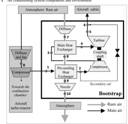
Airconditioning systems for civil aircraft are made of several complex components which interact to regulate the air temperature and pressure in the cabin (Pérez-Grande and Leo, 2002). The system considered in this paper (see Figure 1) is a Joule-Brayton cycle-based airconditioning system (bootstrap). It is mainly made up of two cross-flow
D. Scaravetti and P. Sébastian
plate-type heat exchangers (main and precooling exchangers), one turbine and one compressor coupled together. Nozzles, valves and pipes are used to manage the air flow between these elements.
Figure 1 Air conditioning system components and environment
The air flowing through the cabin comes from the main compressor of one of the turbo reactors of the aircraft. This air flow (main air flow) goes through a precooling heat exchanger, a turbo machine (compressor, turbine, coupling shaft) and the main heat exchanger. Heat extracted from the main air flow is transferred to a ram air flow taken from the frontal surface of the aircraft. Due to the aircraft velocity, the ram air flows through the precooling and main heat exchangers. The temperature of the main air flow is regulated by taking cool air from the outlet of the precooling heat exchanger (secondary air flow) and mixing it with cold air flow from the outlet of the turbine. The secondary air flow regulation is performed by a valve.
The two circuits (main air and ram air) cross each other in alternate layers inside the exchangers. Exchange surfaces are made of stacked fins. For each air circuit, the fins have to be chosen among 48 different standard shapes (Kays and London, 1984). Since there are two exchangers, and two air circuits per exchanger, there are 5.3 million (484)
possible alternatives according to the choice of heat-transfer surfaces types.
Thanks to the discrete nature of some Design Variables (DVs) and to the discernment precision of the others, the number of solution principles of the design problem can be assessed. For example, the dimensions of the inlet sections of the two heat exchangers along two axes belong to continuous domains. However, they are related to discernment
precision (minimum distance between two values of the variables regarded as different values). The domains of these dimensions range from one 0.01 m to 0.5 m. Their discernment precision has been defined by designers at 0.01 m. Thus, the number of combinations of distinct domains for these variables is equal to 2500 (50²).
The size of the global bootstrap design problem has been assessed at approximately 1.04·1015 design configurations when considering all of the possible value combinations
of the DVs. However, not every design configuration corresponds to a design solution. Not every design configuration fits the design requirements and some design configurations do not work for some system environment conditions.
Moreover, the air-conditioning system has to supply air at constant temperature and pressure to the aircraft cabin. Therefore, the design of the bootstrap must take into account different flight phases corresponding to different altitudes and the relative speed of the aircraft. The temperature, pressure and relative speed of the air strongly vary between these flight points.
1.3 Embodiment design difficulties and proposal
Due to the complex interactions of the components, air-conditioning designers have low support to guide them in the process of determining the more efficient fin types inside the heat exchangers. Manual (as opposed to digital) solving processes require knowing the values of the DVs. Therefore, bootstrap designers usually give a priori values for the heat exchanger efficiencies, which is equivalent to considering one configuration of a heat exchanger without considering the variability of the design problem.
Designers frequently develop spreadsheets dedicated to specific issues, but few tools are available to assist them during this design phase, especially because the product behaviour modelling has to take into account complex combinations of physical phenomena. Moreover, design solution validation is performed as soon as all of the architectural choices are made. It is usually processed by developing a digital simulation code of an air-conditioning system and by testing and comparing the performances of a small number of configurations. Finally, the dimensioning of the system is performed for the most critical life cycle stage, the prevailing situation. Using a trial and error mode, designers converge towards a solution which is not necessarily the most powerful one, or which does not necessarily correspond to the best trade-off between the various flight phases.
The approach proposed in this paper leads to the identification of the best design compromises between various design objectives, whatever the life cycle stage. It consists of:
• the expression of the design problem as a set of constraints
• the exploration of the whole design space using Genetic Algorithms (GAs) • the assessment of their performances using criteria relating to the design objectives • the reduction of the solution space using the Pareto front: it allows the identification
of solutions which are the best compromise in simultaneously satisfying the design objectives, without favouring one objective.
D. Scaravetti and P. Sébastian
Until the end of the embodiment design phase, no potential solutions have been dismissed by any choice of the designer. The results of the approach proposed in this paper allow decision support at this stage of the design process.
2 Design problem modelling
2.1 Constraint modelling
In order to avoid the usual trial and error iterative design process and to not dismiss a solution because of a priori choices, we propose to simultaneously take all the constraints into consideration, without any hierarchy or preliminary choices, by modelling the problem as a set of constraints.
The relations linking the variables (equalities, inequalities, logical rules) and their domains of evaluation are the constraints of the design problem. Variables can be real numbers, integers or enumerated values. Parameter values of standard components can be described using discrete variables. Domain use is well adapted to the uncertain knowledge inherent to the embodiment design phase.
The variables which define the product architecture to be designed (dimension, standard component characteristics, materials, number of elements, etc.) are the DVs. The assessment of a solution is performed by using the criteria relating to the design objectives (Scaravetti et al., 2006b): the resolution allows the evaluation of various working structures meeting the working conditions of the system. These solutions may be numerous and may thus need to be classified. In order to objectify the choices among these solutions, criteria which express the performance of each design configuration are used.
Consequently, a design problem is described by a set of DVs, criteria and constraints. A solution corresponds to a set of values – for all DVs and criteria – which meets all the stated constraints. These values define a particular design configuration.
2.2 Modelling of the design problem of the air-conditioning system
A methodology has been proposed to identify the structuring characteristics of the embodiment design problem, which must be translated into constraints (Scaravetti et al., 2005a). The knowledge base of the air-conditioning system consists of:
• twenty-three thermodynamic state variables (pressures, mass flow rates, temperatures, etc.)
• fourteen geometric and structural variables (lengths, surface types, pass number, etc.) • eight criteria (outputs, efficiencies, etc.) which define the performance or which are
used to qualify the quality of a design configuration
• twenty-four auxiliary variables which are defined as functions which correlate their definitions with the 45 preceding variables.
The global model is constituted by 69 constraints. Constraints relating to physics have been derived from energy, momentum or mass flow conservation laws. Due to the complexity of the physical models, which indicates strongly coupled physical phenomena, model reduction methods have been applied (Scaravetti et al., 2006b). The
model of the design problem also includes the functional performance specifications and the description of standard components. The aircraft manufacturer expresses technical skills and manufacturing rules.
The DVs are:
• the type of fin (integer value ranging from 1 to 48)
• the dimensions of each exchanger (from 0.1 m to 0.5 m, with a discernment precision of 0.01 m)
• the diameter of the bypass pipes. The performance criteria are: • the mass of the heat exchangers • the total volume of the two exchangers
• the drag force induced on the aircraft by the air-conditioning system, which can be negative when the system is providing thrust.
The system has to deliver air at constant temperature and pressure to the cabin whatever the flight phase (ground, lift, economic cruise, economic cruise for long haul flights, descent, etc.). The four main flight phases (see Table 1) have been included in the model of the design problem and investigated in this paper.
Table 1 Flight phase characteristics
Aircraft speed Altitude Atm. pressure Atm. temperature
Mach number M Pa (104) K
0.8 11 000 2.272 216.7
0.5 3000 7.028 268.7
0.4 2000 7.967 275.2
0.6 5000 5.418 255.7
3 Generation of design configurations using a genetic algorithm
A first investigation of the design search space was carried out using a CSP solver (Scaravetti et al., 2006a; Sébastian et al., 2007). Only one flight point was investigated at this stage. More to the point, the bootstrap design problem was solved by considering only six kinds of fins inside the heat exchangers, whereas in this paper, 48 different types of fins and four different flight points have been considered. In this paper, several different life cycle situations (flight points) are taken into account, leading to a much more complex design space. Some solutions appear to be effective regarding several life cycle situations, whereas some others are only effective for one life cycle situation. Our approach has been extended by discriminating solutions according to DV values, in order to highlight relevant combinations of DVs. The most relevant solutions belong to the Pareto front and are effective for several flight points.
D. Scaravetti and P. Sébastian
In the following paragraphs, the computing times of every exploration job have been limited to one hour of Central Processing Unit (CPU) time, in order to facilitate the comparison of the results. A GA-based design code has been developed to improve the solving performance of the bootstrap design problem process. The GA heuristic is a metaheuristic with a large scope of interest and applications (Diveux et al., 2001; Hugget
et al., 1999). It is based on the mutation, crossover and selection of individuals from an
evolving population. Evolving generations tend to improve an optimisation criterion (the fitness function) by mixing individual genes and generating random individuals to search the complete exploration space of solutions. This heuristic method is involved in many different types of mechanical design tools. However, in industrial conditions, it is mainly used as an optimisation tool for the management of several simulation codes. Simulation codes simulate the behaviour of different parts of the mechanical system, whereas the GA-based optimisation tool supervises the system architecture and the design performance criteria.
The design code proposed in this paper is used to solve a design CSP, rather than optimising a design problem. This means that the design code conducts a search for sets of solutions rather than optimised solutions. This is performed using an optimisation criterion guaranteeing the satisfaction of every constraint of the design problem. Every constraint ‘Ci’ of the problem is related to a value ‘SAT(Ci)’: if Ci is satisfied,
SAT(Ci) = 1, else SAT(Ci) = 0. The fitness function optimised by the GA is described
in Equation (1):
( )
1 1 . 2 n i i SAT C SAT = + =∏
(1)The solutions considered in the following paragraphs satisfy every constraint of the problem (SAT = 1). The population size has been fixed to 100 individuals (candidate solutions) and the crossover probability is 0.5.
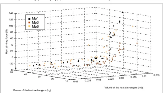
Due to the extreme sensitivity of the system functioning to the DV values (chiefly the selection of the heat exchanger fins), the mutation probability of the GA proves to be a key parameter of the solving process. A pure random search-based algorithm leads to relevant results (the design space is almost completely explored) but the computation times are high (Scaravetti and Sebastian, 2007). As a consequence, we take into consideration several values of the mutation probability, ranging from low values to very high values. In this paper, three different mutation probabilities are considered. The variable Mp equals 0.1 (Mp1), 0.3 (Mp3) or 0.6 (Mp6). Figure 2 highlights solutions minimising the performance criteria for each Mp. This selection was obtained by computing the set of nondominated solutions according to a Pareto method (see Section 4.1).
Figure 2 displays all the nondominated sets of solution spaces obtained for the three values of the mutation probability. Every solution is represented according to three performance criteria: the global mass and the volume of the heat exchangers, and the drag force induced. Figure 3 shows the same three sets on a 3D space. We note that the reading of the projections is easier.
Figure 2 Pareto sets of solution spaces obtained for each mutation probability, displayed among
performance criteria pair by pair
-50 0 50 100 150 10 20 30 40 50 mass DDra Mp1 Mp3 Mp6 R a m a ir d ra g f o rc e ( N )
Mass of the exchangers (kg)
-50 0 50 100 150 0 0,01 0,02 0,03 0,04 total volume DDr a Mp1 Mp3 Mp6 R am a ir d rag f o rc e (N )
Volume of the exchangers (m3)
0 0,01 0,02 0,03 0,04 10 20 30 40 50 mass to ta l v o lu m e Mp1 Mp3 Mp6
Mass of the exchangers (kg)
V ol u m e of th e e xc h a n ge rs (m 3)
300 D. Scaravetti and P. Sébastian
Figure 3 Three-dimensional Pareto fronts of solution spaces obtained for each mutation
probability (3D display) (see online version for colours)
10 20 30 40 50 0.005 0.01 0.015 0.02 0.025 0.03 0.035 0.04 -40 -20 0 20 40 60 80 100 120 140
Volume of the heat exchangers (m3) Masses of the heat exchangers (kg)
R am a ir d ra g f orc e (N ) Mp1 Mp3 Mp6
Each mutation probability leads to a different solution space, which performances are quite different. In the continuation of the paper, only the value Mp = 0.3 is considered in order to limit the size of the data exploitation and to better show the use of visualisation of relevant DV values.
4 Design space exploration
Once the investigation of the design configurations has been performed, we aim to support the decision of the designers by guiding the exploitation of the results. This means:
• guiding the choice of DVs among the variables of the problem by finding the relevant DVs or the relevant combinations of variables
• supporting decisions by reducing the solution space and finding suitable solutions.
4.1 Solution space reduction
The types of fins and the arrangement of the stacked plates in the heat exchangers have a decisive influence on the mass and the volume of the system. They also affect the efficiencies of the exchangers and therefore the air-conditioning efficiency of the system. Moreover, some of the air feeding the conditioning systems is scooped off the surface of the aircraft using a scoop. This air bleeding induces a drag force at the surface of the aircraft, which is detrimental to the global performance of the aircraft. This drag force has to be minimised. Therefore, a compromise has to be found between these antagonistic requirements.
The solution classification has been investigated with an objective function (Scaravetti et al., 2005a), but a weight factor-based method raises the problem of the value assignment of the weight factors.
Every Pareto solution is nondominated (Goldberg, 1989) and the front definition aims at minimising the performance criteria values. The selected solutions correspond to a trade-off between disparate and conflicting design performances (Hamdi et al., 2006). A solution is nondominated if no other solution relates to the best values for all criteria (mass, volume and drag induced in our case).
The reduction of the solution space is quite efficient. Table 2 displays the sizes of the solution spaces and Pareto sets. This selection process drops the number of solutions from 2634 solutions to 35 solutions (Mp = 0.3). Less than 1% of the complete solution space (considering all Mp’s) belongs to the front (nondominated solutions).
Table 2 Number of solutions according to the mutation probability
Mp 1 Mp 3 Mp 6 All Mp’s
Nb solutions 2325 2634 677 5636
Nb sol. Pareto set 29 35 28 37
1.25% 1.33% 4 .13% 0.66%
Figures 4 to 6 display the solutions in the performance space and locate the Pareto solutions matching the performance criteria pair by pair. A solution minimising two performance criteria may be detrimental to the third performance criterion. For instance, the solution corresponding to a mass of 13.8 kg is the Pareto solution according to the masses and volumes of the heat exchanger, but is detrimental to the drag force.
Figure 4 Performance space (volume versus drag force) and Pareto set
-50 0 50 100 150 200 250 300 0,005 0,01 0,015 0,02 0,025 0,03 0,035 0,04 0,045 0,05 0,055 total volume DD ra Mp 3 Pareto R am a ir d ra g fo rc e ( N )
D. Scaravetti and P. Sébastian
Figure 5 Performance space (mass versus drag force) and Pareto set
-50 0 50 100 150 200 250 300 10 15 20 25 30 35 40 45 50 mass DD ra Mp 3 Pareto R am a ir d ra g fo rc e ( N )
Mass of the exchangers (kg)
Figure 6 Performance space (mass versus volume) and Pareto set
0,005 0,01 0,015 0,02 0,025 0,03 0,035 0,04 0,045 0,05 0,055 10 15 20 25 30 35 40 45 50 mass tota l v o lu m e Mp 3 Pareto
Mass of the exchangers (kg)
V ol um e of th e e xc h a n ger s (m 3 )
The Pareto set is located at the frontier of the solution space when displaying the solutions according to mass versus drag and mass versus volume (Figures 4 and 5). The reduction of the solution space and its visualisation within the performance space facilitates the choice between feasible design configurations.
4.2 Design space exploration and decision support
Despite the reduction of the solution space, design decisions remain difficult. To overcome this difficulty, we propose to supply designers with an overview of the design space: the solutions are displayed according to combined DVs to assist designers in making choices among them.
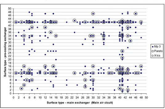
Figures 7 and 8 display the solutions (for Mp = 0.3) in the design space, according to the fin types of the two heat exchangers (main and precooling exchanger). Figure 7 concerns the main air circuit and Figure 8, the ram air circuit.
Figure 7 Design space and visualisation of relevant designer variable values (surface type) for
main air circuit (see online version for colours)
0 2 4 6 8 10 12 14 16 18 20 22 24 26 28 30 32 34 36 38 40 42 44 46 48 50 0 2 4 6 8 10 12 14 16 18 20 22 24 26 28 30 32 34 36 38 40 42 44 46 48 50
Surface type - main exchanger (Main air cicuit)
S urf ac e t ype pre -c ool ing e xc ha nge r Mp 3 Pareto X lcs
We can observe in Figures 7 and 8 that there are few relevant fin combinations. In spite of 2634 solutions, the design space is not much filled. Thus, several solutions use the same fin combinations.
Designers can easily identify the relevant combinations for each circuit and the fin types which do not match any solution. For example, type 7 is relevant for the precooling exchanger on the ram air circuit as many embodiment design solutions use this surface type; many of them are nondominated solutions (see Figure 8).
Moreover, the identification of efficient surfaces is facilitated by highlighting the Pareto solutions and the solutions compatible with several life cycle stages (called ‘X-lcs’ in Figures 7 to 9). The Pareto solutions are the design solutions managing the best compromise between the requirements (minimising the drag, mass and volume of exchangers). These solutions are shown in Figures 7 to 9 to put emphasis on the optimal associations of fin types. Even if Pareto solutions and solutions functioning in many life cycle stages do not match, we can see that they use the same fin combinations; consequently, they differ in the values of other DVs.
D. Scaravetti and P. Sébastian
Figure 8 Design space and visualisation of relevant design variable values (surface type) for ram
air circuit (see online version for colours)
0 2 4 6 8 10 12 14 16 18 20 22 24 26 28 30 32 34 36 38 40 42 44 46 48 50 0 2 4 6 8 10 12 14 16 18 20 22 24 26 28 30 32 34 36 38 40 42 44 46 48 50
Surface type - main exchanger (Ram air cicuit)
S u rf ace t yp e p re-co o li n g ex ch an g er Mp 3 Pareto X lcs
Figure 9 Visualisation of relevant fin combinations for the main air circuit and Pareto set for all
of the solutions (all Mp’s)
0 2 4 6 8 10 12 14 16 18 20 22 24 26 28 30 32 34 36 38 40 42 44 46 48 50 0 2 4 6 8 10 12 14 16 18 20 22 24 26 28 30 32 34 36 38 40 42 44 46 48 50
Surface type - m ain exchanger (Main air cicuit)
S u rf ace t yp e - p re-co o lin g exch an g er Mp3 Pareto Mp3 - X lcs Pareto all Mp
Some fin types are well adapted to the definition of design solutions, but they are different for each circuit:
• For the main exchanger, fin type 41 is the most appropriate for the main air circuit and fin type 45 appears to be well adapted to the ram air circuit.
• For the precooling exchanger, fin types 12 and 42 may be used in the main air circuit, whereas fin type 7 is more adapted to the ram air circuit.
The intersection of these configurations of fins jointly belongs to the Pareto set and to the X-lcs set; for example, fin type 41 (main exchanger) is related to type 12 (precooling exchanger) for the main air circuit (see Figure 9).
Finally, some types of fins do not match any design solution and, therefore, seem to be irrelevant for the bootstrap application. For instance, whatever the air circuit being considered, types 17 to 19 are never involved in the functioning of the main heat exchanger.
These observations are confirmed by Figure 9, which superposes, on the solutions selected for Mp = 0.3, the Pareto set obtained for all the solutions (all Mp’s, i.e., 5636 solutions). The Pareto set for Mp = 0.3 matches the Pareto set for every value of Mp (all Mp’s).
The preceding analysis cannot guide designers to the optimal solution of the bootstrap design problem. However, this investigation supports designer decisions by suggesting relevant guidelines and avoiding some irrelevant choices. These visualisations show that few fin types are well adapted to one particular air circuit and one particular exchanger. In particular, it supports designers in the process of choosing the fins. This choice highly influences the system functioning and is difficult to know a priori. Besides, we can see that the relevant types are not the same ones for the two circuits, which are functioning under different conditions.
Finally, a small number of DV configurations meets the whole of the design constraints for the various flight phases. This consideration corroborates the difficulty of finding design solutions suitable for the complete bootstrap life cycle; this difficulty appears to be the bottleneck of the bootstrap design process.
5 Conclusions
In this paper, the design of an aircraft air-conditioning system has been discussed. This air-conditioning system is based on a Joule-Brayton cycle, including a turbo engine and two heat exchangers. Designers are faced with the complexity and the coupling of physical phenomena inside this system. More to the point, the system must run during four flight phases corresponding to different pressures and temperatures of the air outside of the aircraft. Due to the complexity and the large size of the design exploration space, classical design processes are based on the investigation of a small number of design configurations.
In this paper, a wide design space (1.04·1015 design configurations) has been explored
without considering a priori choices. This digital approach is based on GAs. Based on the selection, mutation and crossing of design solution principles, the exploration is performed by improving the satisfaction of the constraints of the design problem. The design problem is regarded as a CSP and a design solution must satisfy every constraint of the design problem.
D. Scaravetti and P. Sébastian
This approach has proved to be influenced by some genetic parameters, mainly the mutation probability. Due to the coupling of the physical phenomena inside the air-conditioning system, the solving of the CSP appears to converge towards numerous solutions for high values of the mutation probability (30% to 60%). Despite the fact that the computing process converges towards 5636 feasible embodiment design solutions (1 hour of calculation), a few configurations proved to be adapted to the complete design problem; namely, a design problem facing several life cycle situations (several flight points).
Such an approach may be relevant to designing complex industrial systems or when the life cycle of the system is faced with varying situations. It supports designers in the process of determining feasible embodiments: designers can make decisions based on the identification of relevant or irrelevant values of the DVs. These decisions are also based on the management of the compromise between the design requirements. However, it has been observed that optimal solutions according to one particular life cycle situation may be unrelated to optimal solutions according to several life cycle situations.
Our perspectives concern the development of new operators inside GAs suitable for improving the robustness of the design solutions and for improving the performance of the solver with regard to the CSP paradigm. The CSP paradigm aims at separating knowledge (design constraints) and programming (solving methods).
References
Antonsson, E.K. and Cagan, J. (2001) Formal Engineering Design Synthesis, Cambridge, UK: Cambridge University Press.
Chenouard, R., Sébastian, P. and Granvilliers, L. (2007) ‘Solving an air conditioning system problem in an embodiment design context using constraint satisfaction techniques’, in C. Bessiere (Ed.) Proceedings of the Constraint Programming Conference CP 2007, LNCS 4741, Berlin, Heidelberg: Springer-Verlag, pp.18–32.
Diveux, T., Sébastian, P., Bernard, D., Puiggali, J.R. and Grandidier, J.Y. (2001) ‘Horizontal axis wind turbine systems: optimization using genetic algorithms’, Wind Energy, Vol. 4, pp.151–171.
Goldberg, D.E. (1989) Genetic Algorithms in Search, Optimization and Machine Learning, USA: Addison-Wesley Company Inc.
Hamdi, A., Yannou, B. and Landel, E. (2006) ‘Exploration in the preliminary mechanical design of trade-offs between automotive architecture constraints and aggregate noise performances’,
Proceedings of the ASME International Design Engineering Technical Conferences & Computers and Information in Engineering Conferences/Design Automation Conference, IDETC/DAC, Philadelphia.
Hugget, A., Sébastian, P. and Nadeau, J.P. (1999) ‘Global optimization of a dryer by using neural networks and genetic algorithms’, AIChE Journal, Vol. 45, No. 6, pp.1227–1238.
Kays, W. and London, A. (1984) Compact Heat Exchangers, McGraw-Hill Book Company. O’Sullivan, B. (2001) ‘Constraint-aided conceptual design’, PhD thesis, Professional Engineering
Publishing, ISBN: 1-86058-335-0.
Pahl, G. and Beitz, W. (1996) Engineering Design: A Systematic Approach, Berlin/Heidelberg: Springer-Verlag.
Pérez-Grande, I. and Leo, T. (2002) ‘Optimization of a commercial aircraft environmental control system’, Applied Thermal Engineering, Vol. 22, pp.1885–1904.
Scaravetti, D. (2004) ‘Formulation préalable d’un problème de conception, pour l’aide à la décision en conception préliminaire, PhD thesis, ENSAM, Bordeaux, France.
Scaravetti, D., Nadeau, J.P., Pailhes, J. and Sebastian, P. (2005a) ‘Structuring of embodiment design problem based on the product lifecycle’, Int. J. Product Development, Geneva: Inderscience, Vol. 2, Nos. 1–2, pp.47–70, ISSN: 1477-9056.
Scaravetti, D. and Sebastian, P. (2007) ‘Generation of design spaces and trade off between feasible embodiments: the bootstrap design problem’, Proceedings of the 16th International
Conference on Engineering Design (ICED 07), Paris, ISBN: 1-904670-02-4.
Scaravetti, D., Sebastian, P. and Nadeau, J.P. (2006a) ‘Generation and evaluation of feasible embodiments’, Proceedings of the International Conference on Integrated Design and
Manufacturing in Mechanical Engineering, Grenoble.
Scaravetti, D., Sébastian, P. and Nadeau, J.P. (2006b) ‘Structuration d’un problème de conception préliminaire, formulation et résolution par satisfaction de contraintes. Ingénierie de la Conception et Cycle de Vie du Produit’, Traité IC2, Chap. 7, Hermès, pp.149–168, ISBN: 2-7462-1214-5.
Sébastian, P., Chenouard, R., Nadeau, J.P. and Fischer, X. (2007) ‘The embodiment design constraint satisfaction problem of the bootstrap facing interval analysis and genetic algorithm based decision support tools’, International Journal on Interactive Design and Manufacturing, Vol. 1, No. 2, pp.99–106.
Thornton, A.C. (1996) ‘The use of constraint-based design knowledge to improve the search for feasible designs’, Engineering Application of Artificial Intelligence, Vol. 9, pp.393–402.