OATAO is an open access repository that collects the work of Toulouse
researchers and makes it freely available over the web where possible
Any correspondence concerning this service should be sent
to the repository administrator:
[email protected]
This is an author’s version published in:
http://oatao.univ-toulouse.fr/2
2311
To cite this version:
Tran, Hanh Nhi and Hajmoosaei, Mojtaba and Percebois, Christian and Front, Agnes and Roncancio, Claudia Integrating run-time changes into system and software process enactment. (2016) Journal of Software: Evolution and Process, 28 (9). 762-782. ISSN 2047-7481.
Official URL:
https://doi.org/10.1002/smr.1783
lntegrating run-time changes into system and software process
enactment
Hanh Nhi Tran1
·*·\
Mojtaba Hajmoosaei1, Christian Percebois1, Agnes Front2 and Claudia Roncancio2
1 lnstitut de Recherche en Informatique de Toulouse (IR/1), University of Toulouse, Toulouse, France
2Laboratoire d'Informatique de Grenoble (LIG), University of Grenoble, Grenoble, France
ABSTRACT
In System and Software Engineering development, unforeseen changes occurring during process enactment are almost inevitable but often poorly managed due to a Jack of efficient mechanisms for spontaneously handling these run rime changes. We proposed a change aware process management system that allows process actors reporting emergent changes, analyzing possible impacts, and notifying people affected by the changes. To this end, we integrated a Change Management Component with a Process Management System. The Process Management System monitors process enactment and uses the run rime process information to construct a Process dependency graph (PDG) representing the dependencies among the elements of running processes. The Change Management Component captures change requests sent asynchronously, then re asons the PDG to determine impacte d elements. Our PDG reflects the information of process instances and therefore can uncover the intra process or inter processes dependencies that are invisible on process models. We implemented a prototype named CAPE based on the platform jBPM and the graph database Neo4j. Copyright© 2016 John Wiley & Sons, Ltd.
KEY WORDS: change impact analysis; Process Management System; process enactment
1. INTRODUCTION
Nowadays, changes in System and Software Engineering (SSE) projects are almost inevitable due to evolving requirements, resources, and technologies. Changes occurring in a running task can affect, in a chaining fashion, other tasks either inside one organiz.ation or among different organizations. Badly managed changes can lead to unwanted reworks and cause projects to fall be hind schedule and go over budget. A pplying a holistic, structured approach to manage changes is then crucial to avoid adding extra cost and risk to both the project and organi zational levels.
As pointed out in [1], the complexity of the product, in terms of the number of components and the relationships between them, is a major source of change management problems. ln general, the development of a system involves multi-teams, multi-disciplines, and can be realized on multi-sites. Consequently, facing a change, a single person can rarely have a detailed overview of all the system's components, such that be would be able to assess the impact and inform the concerned actors. Having a partial view on the development process, often, process actors do not know how their work relates to other tasks and have difficulties, even impossibility, in identifying the right person to communicate with for quickly resolving a problem. Lack of information on task
*Correspondence to: Hanh Nhi Tran, Institut de Recherche en Informatique de Toulouse (IRIT), University of Toulouse,
118 Route de Narbonne, F 31062 Toulouse Cedex 9, France.
connections can lead to unnecessary repetition or inconsistent results, which in turn will require rework or changes in other tasks. Insufficient communication usually discourages process actors to report all the changes they made or obliges them to follow hierarchical channels for propagating a change, where it can be delayed or misinterpreted.
Most modern SSE processes are extremely complex and inherently uncertain. These characteristics make managing SSE processes especially challenging. On the one hand, it is hard tofinely describe SSE processes in order to exactly reflect the process execution in reality. Changes emerging at run-time are not predictable and therefore not integrated into process models. On the other hand, it is hard to develop an effective Process Management System (PMS) to automatically coordinate SSE processes that require low-level operational, flexible, and collaborative workflows [2]. In this context, although each organization does have a certain change management process, it is often poorly applied and relies on humans to propagate changes, especially emergent changes. Change management in SSE is thus a critical issue that is far from being mastered [3].
To facilitate run-time change management in SSE development, we aim at a change aware process environment, which provides an overall control on the development along with mechanisms for (1) capturing changes occurring in the development environment and (2) analyzing change impacts and informing affected process actors, all in a timely and systematical manner. We do not have the ambition to propose a complete solution for change management. We are primarily interested in the change notification issue. Change implementation is out of the scope of the presented work. Our objective is to provide an effective assistance for coordinating process actors in order to keep their work products consistent. Thus, we propose aflexible enactment of the SSE process to deal with changes made on the work products of the SSE process. Such changes are not described in the process model. So, if actors follow strictly the process model, they cannot handle the changes. We provide a certainflexibility on instantiation and execution of tasks in order to allow integrating the run-time changes in the actual process. But we do not handle changes made on the process model itself, that is, the process structure is supposed to be intact during its execution.
This paper extends our previous work [4] to enable more collaborative patterns, especially those concerning multiple instances tasks. We also enhanced the functionalities of our environment to support both emergent and initiated changes to respectively correct or evolve the process’s work products. The remaining part of the paper presents our solution to obtain the objectives mentioned earlier and is organized as follows. Section 2 gives a brief description of our approach based on a motivating example. Section 3 presents the process dependency graph (PDG), an abstract graph describing the links between running processes and providing us with a global structure to analyze the impact of a change. Our idea is using PDG inside a process environment to enable change notification and analysis at run-time. We describe in Section 4 the architecture of our change aware process environment and report in Section 5 the experiments carried out by using our prototype CAPE. Some related works are discussed in Section 6, and Section 7 concludes our paper.
2. APPROACH
In this section,first, we describe, through an example inspired from a real process of our industrial partners, a typical situation of changes in process enactment and point out some synchronization problems if the change is not well managed. Finally, we present our approach to tackle this issue. 2.1. Motivating example
In [3], the authors classified change processes existing inside companies into two types: official and unofficial. An official change process is a macro-level process defining formal protocols to be respected to handle changes concerning to a company or a product. Normally at this level, the change process is rather well defined and conducted. An unofficial change process happens generally inside technical processes, during the pre-certification phases, as backwards patching/ debugging redesign processes where developers attempted to fix a problem quickly during the
development. This type of process is often informal or semi-formal and poorly managed due to the lack of coordination among developers. In this work, we focus on the problem of change management in the context of an unofficial change process.
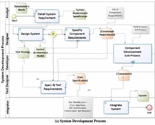
Figure 1 shows a portion of a system engineering process simplified from the V-model. This example describes the system development phase containing two technical processes as System Development process (Figure 1a) and Verification & Validation process (Figure 1c). In our example, these two processes are performed respectively by System Team and Test Team. The System Team defines five roles as Analyst, Designer, Test Designer, Developer, and Integrator; the Test Team has only one role as Tester.
In the System Development process, the activity Design System produces two work products: System Architectural Model, which specifies the high-level design of the system, and Test Strategy, which describes several functionalities of the system to be tested later by the Test Team. From the System Architectural Model, the activity Specify Component Requirements generates the requirements for each component of the system. These requirements are aggregated in the work product Component Requirements. For each component requirement, the Component Development sub-process (Figure 1b) is realized to design the Component Design Model and then implement the final component. As the development of different components can be realized concurrently and independently, the sub-process Component Development is modeled as a multi-instance task. The number of instances of the sub-process is determined at run-time by the number of elements in the work product Component Requirements.
In parallel, the Test Strategy is analyzed in the activity Specify Test Requirements to produce the Test Specifications for each functionality to be tested. In a test specification, the system under test is represented by a list of Component Design Models of the components implementing the tested functionality. The test specifications are combined into the work product Test Specifications.
The Test Team starts to work in parallel with the System Development Team when the Test Specifications are defined. For each element in the Test Specifications set, an instance of the Verification & Validation (V&V) process is created. The Tester analyzes the test specification to get the Test Objectives, the list of Component Design Models of the system under test, and the Environment Specification needed for preparing the Test Bench that will be used for executing the test. These two general processes can be used for various development projects, thus, may be adapted to a specific context of a given project as illustrated in the following scenario.
ScenarioΔ
We examine the project1whose Specify Component Requirements task and Specify Test Requirements
task are carried out. Thus, the components to be developed and the tests to be executed are known. The main information about the project1are presented in Table I.
We suppose that at that moment, the company has two other projects, project2and project3, which
are waiting to use the test bench tb1for their V&V processes denoted as P2.1. vvand P3.1. vv.1
Change We consider one of the most common unofficial change situation that frequently occurs during system development:
In the project1, when carrying out the Implement Component task to build the component C1, the
developer d1faces a problem in the Component Design Model CDM1. To continue and finish his
implementation, d1 wants to modify CDM1, which is out of his responsibility. If the change was
controlled, d1 had to inform the designer des1of the problem and then wait for a new version of
CDM1. However, in reality, in a loosely controlled development environment, d1 may change
directly CDM1without reporting the change because (1) he cannot wait and (2) he does not know
the concerned people to notify them of the change.
In this example, the possible impacts of the change on CDM1initiated by d1are
• Impacts inside project1: any change in CDM1will immediately affect the process instance P1. vv
performed by tester t1who is preparing the test environment for the functionality F1that is based
1
1
Stokeholdor'•i
Need< b Oet1II System Requiromonti
1
Sto.l't r____ "I---...---Jr
-�
Design System., il
L
....
tl ·;;; o ._ � .:. ,+
••••••• ..,_ System : Requlremmt ··' st,edftcollqn Spedfly Component Requlremonts li!lol c .... po...,, R.(>'(J.•1�f'nU .,. ---c> .:.. : (C,omponent j �- --- Requl,emenO i Mutll-ln\t•nt(' Sul>-Pr°""" .···' Q. V Q'1: ., ._, __ T�•" Stutqy-A,ohltectuoSyste:n19---- ---' --+----1
E ._ _,
g- g-
�.:,
Component Oevolopmont Sub-Procoss'i j
� c!: E ! t � � "'3 Vl � 1. . ... ... �2.-Spe-ct_,"fi'-y-_Test_...,
., Requirements
!
(Test Speclfttollon)-r···
( Ccmpenent) 0 C>, ---.---+---,Sy>tom ÎMl S,.C.if1t.itio• • f tMtoa,;,,.«M',, SOI »o<,f,...11o<o, C..YltOOl-•I St,eol1C.i11ion >(a) System Development Process
.. �
�
:::!,
··,
:
···
s-C:=:.
C ,__..__..., � !JI0--
Oosign �E1
c.:
..
_,---
Component lntegr11e System.,
�l
Ll
�---�---.--
.
_.
-
.
..
-
..
-
-
...
J"-Ponenl C t_i
1
!
I
1
�
1
°
fmplemont �---"" Componont(b) Component Development Sub-process
,
..
v,-= - --TeiaObJectl•ti : , •.••. -c,.Te> tBen&·--····, ·············t,tRe put Conftaw•tlon ---. 4>- .,; SUTSpedfl<otlon Speclfttotlon Envbonment
-Tan Bench
. '
. .
End; : _________ !�slProcedure SVT , ... .
(c) Verifü:ation & Validation Process
l
End
Figure 1. Processes of a System Development phase. (a) System Development Process. (b) Component Development Sub process. (c) Verification & Validation Process.
on CDM, and CDM2• Changing CDM, without notifying t1 may lead to an incompatible test en vironmenttb1, which is obsolete and not corresponding to the real componentC1 developed by d1.
Such a change, however, will not impact the work of the integrator i1who is waiting for the
im-plementation of C1. This change will not impact neither the work of the tester t2who is preparing
the test environment for the functionality F2based on CDM2and CDM3. This change may require
reworks of the designer des1to insure the consistency between the work product Component Re
quirement CR1and the Component Design Model CDM1.
• Impacts on other projects: the change on CDM1in project1leads to reworking of the tester t1to
prepare the new version of configuration for the test bench tb1. Consequently, t1may have to keep
tb1. for a longer period. Because tb1. is also required in the V&V process instances P2.1. vvof pro
ject2and P3.1. vvof project3, the change in project1can have significant impact on project2and
project3. The impact concerning shared resources requires often stressful and costly planning
ad-justment for the whole company.
The aforementioned impacts cannot be deduced from the process models as information arises only at run-time, such as the list of components, the state of tasks, the shared resources, and so on. By performing the analysis at the model level, we can deduce just some coarse impacts of change. For example, we can say that a change on the work product type Component Design Model will impact the activities Prepare Test Bench and Execute Test. But if these activities have many concurrent task instances performed by different testers, we cannot say exactly who and which task instances are affected. Moreover, at the model level, we cannot know the inter-process impacts via shared resources. We are interested in this unofficial change and motivated by development environments where changes are handled manually and communication between concerned actors is free and ad hoc. In such environments, the poor coordination can lead to unawareness of changes and therefore to possible reworking. We aim to develop a mechanism that helps coordinating better the process actors and therefore managing changes more efficiently. As observed, in order to thoroughly assess change impacts, managing and analyzing changes should be done at instance level (run-time). In the next section, we present our solution to achieve this objective.
2.2. Proposal
In this paper, we seek to remedy the problem of unnoticed changes in order to permit concerned people to anticipate and respond to changes so that they can avoid obsolete works. The ultimate goal of our work is providing a change aware process environment being reactive to change requests but proactive to change implementations with the following functionalities:
• Capturing in a centralized and continuous way all change requests sent asynchronously by var ious process actors: This functionality requires consolidating process management mechanism and change management mechanism. On the one hand, a PMS is needed to monitor process ac-tors’ activities. On the other hand, a Change Management Component is needed to allow process actors reporting changes and analyzing the impact of their change on the whole system.
• Analyzing the potential impacts when a change happens and notifying process actors affected by the change: To enable analyzing the impacts of change among process elements in a timely and systematically manner, we need to integrate the process management mechanism and the query mechanism on the run-time process data. The result of this consolidation is the PDG that
Table I. Information of Project 1.
Human resources Analyst = a1, Designer = des1, des2, des3, Test Designer = td1,
Developer = d1, d2, d3, Integrator = i1, Tester = t1, t2
Non human resources Test Bench = {tb1, tb2}
Components {C1, C2, C3}
Test objectives Functionality F1on C1, C2
Functionality F2on C2, C3
System development processes Number of instances = 1, P1.1. sd
Number of sub process instances = 3
Verification & Validation processes Number of instances = 2, Test objectives = F1, F2
We emphasize the use of run-time process information in order to establish a global view on the state of all elements inside the development environment. As pointed out in the example in Section 2.1, while some of the dependencies existing among elements inside one process instance can be easily extracted at build-time from the process model, there are other dependencies that only emerge at run-time. It is especially the case of dependencies among different instances of a multi-instance task or multi-instance sub-process. It is also the case of dependencies via shared resources among different running processes. In contrast to most of the existing works that have concentrated on the dependencies at process model level [5, 6], our PDG describes dependencies at run-time in the process instance-level, thus allowing a more thorough change impact analysis. For an efficient storing and querying of run-time process data, the PDG is implemented in a graph database. When a change request is made, PDG provides a sound and effective basis to traverse intra-process instance and inter-process instances to derive the affected elements.
3. PROCESS DEPENDENCY GRAPH
This section presents the PDG, which is our solution to represent a global view about the system at run-time.
3.1. Process information
In the development environment, process information exists at two levels: model and instance levels. When a process is executed, its model is instantiated and a process instance representing the running process is obtained.
The model level relates to process information existing at build time and extracted from process models. For our example, model-level information is represented in Figure 1. The instance-level concerns process information existing at run-time. For example, the sub-process Component Development has three instances at run-time; each instance has two tasks: Design Component (DC) and Implement Component. Therefore, in the run-time environment, there are six task instances denoted as three DC1, DC2, DC3and three IC1, IC2, IC3. The whole instance-level information of
the process models of Figure 1 is represented in Figure 2.
If a PMS is used to manage and enact processes, the model-level information is stored in the process repository, and the instance-level information of running processes are stored in the execution log and the history log. When a change occurs, all this information are required in order to establish the dependencies among process instances to enable an in-depth impact analysis. We have two approaches to construct process dependencies:
• Querying the process logs at the time of change analysis to deduce the dependencies: This approach requires extracting process information directly from different PMS’s logs. It is advantageous in terms of data storage. However, making complex queries from the process repository and process logs is not easy because of the heterogeneity of the process data together with the process log’s access characteristics within the context of activities that are long lived, open ended, and interactive [7].
• Constructing a global dependency structure in parallel with the processes’ execution to establish progressively the dependencies among process instances: In some way, this approach duplicates the process information stored in the system. However, it can lead to an improvement in performance if an efficient support is chosen to represent and implement the global dependency structure.
After considering the trade-off between efficiency and storage, we choose the second approach and propose the usage of a graph structure called the PDG to represent the dependencies among process elements at run-time. PDG is continuously updated to reflect always current state of the system.
represents dependencies existing among all process elements of the system at run-time and there-fore provides process actors with information of the whole development environment what they cannot know from their local viewpoint.
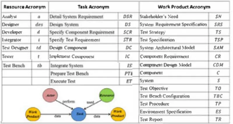
Resource Acronym TllskAaonym Wor1t Product Aaonym
AMl)·M
•
OSR Stw:bolda-'s N...t SNo.-,'ll',... os __ sr.icai Rcquarc:mcnt SpcaficahOII SRS
D<s-<lop<t d SCR Î<$1 Slr>ICI) TS
IIM�or Specify Tac Rcquircmcct STR Tes, Sp<cif,..,i<,n TSP TcstDcsia,,cr td Oci1i,tC0t_,.. oc S)'St<m Ardù1«11nl Moclcl SAM
Tatcr IQimlcotC_,..,.... /C C<IIIJPGfl('III Rcqwcmm1 CR
c_....,�Moodcl CDJI
c_...., C
S)"S(c:m s
T� Ob,«bn TO
Tc:11 lkndi Contip111oca TBC
Tc,,- Tl'
E111,-wonmcat Spttifar.ion es
IT<>1R<1)0<l TR
(a) Process elements acronyms
PDG
Project 1
(b) Process information at instance-level of the scenario /1
Figure 2. Process dependency graph representing the scenario L1. (a) Process elements acronyms. (b) Process information at ins tance Jevel of the scenario L1.
3.2. Structure of process dependency graph
The PDG is defined as a directed graph composed of a set N of nodes and a set E of edges. Nodes and edges of a PDG are typed to describe different types of process elements ( at instance level) and relations between them. We have four types of nodes and four types of edges, specified in the following definitions:
PDG= (N,E)
N
= {
node1ask}u{
node,varkProd11c1]u{ nodeactor}u{
nodereso11rce}E
= {
edgedata}u{ edgeprecede}u{ edgeperfom,}u{
edge11sec1}3.2.1. Nodes of Process Dependency Graph. Each type of nodes has properties, which are defined as
follows:
• node,ask represents an instance of a task.
node,ask = (type, name, id, state, durati.on, parentProcesslnstance
type = (si.nglelnstance, multilnstance)
In this paper, we handle human tasks and adopt the standard Web-Service Human Task (WS-HT) [8]. Furthermore, if a task can have multiple instances independent at run-time, its type is multiInstance.
• nodeworkProductrepresents a concrete work product (data) inside a process instance. The state of a
work product is the same as the state of the task producing it. nodeworkProduct = (type, name, id, state)
type = (singleWorkProduct, workProductSet) state = (created, inProgress, completed, aborted)
•
nodeactorrepresents a real actor in the system. An actor may involve in several process instances. Weassume that the state of an actor is managed by both the task management component and the resource management component integrated to the PMS.
nodeactor = (role, id, state)
state = (notAvailable, idle, active, waiting)
•
noderesourcerepresents a resource that an actor uses to perform a task.noderesource = (id, state)
state = (notAvailable, idle,active, waiting)
3.2.2. Edges of Process Dependency Graph. Edges in PDG are used to represent different types of relationships among process elements. Properties and state of each type of edges are defined as follows: • edgeperformrepresents the association between an actor and the task that he performs. The state of the
edge is the same as the state of the task that it points to. The reason to store this information twice is to facilitate the traversal that we will discuss later.
edgeperform = (id, process, Instance, StartTime, duration)
state = (inProgress, completed, waiting)
•
edgedatarepresents the association between a work product (data) and a task using or producing it:edgedata = (id, source, target, state)
state = (sent, notSent)
•
edgeprecederepresents the association between two sequential tasks that share nothing between eachother (i.e., no exchanged work products or shared resources). edgeprecede = (id, source, target)
•
edgeused: represents the association between a resource and an activity.edgeused = (id, source, target, state)
Figure 2 is provided to illustrate the PDG representing the system in the scenarioΔ at run-time. To simplify the visualization of the PDG, process elements of only project1 along with only affected
elements in other projects are illustrated. In our scenario, shared elements among process instances are established by the work products Component Design Model CDM1, CDM2, CDM3 and
Component C1, C2, C3. The shared element between projects is established by the resource Test
4. CHANGE-AWARE PROCESS ENVIRONMENT
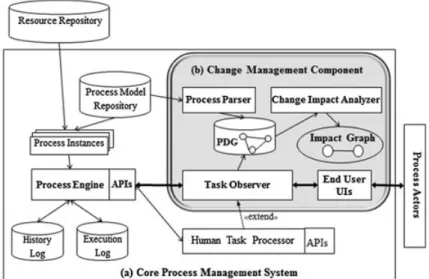
This section describes our solution to deal with poorly managed changes during process enactments. Although this work targets more specially on technical software and system engineering process, it can also be used by processes in other domains. Our aim is to consolidate two mechanisms of process management and change management to create a change-aware process environment as illustrated in Figure 3.
Our environment is composed of two main components: a PMS to execute and control processes and a Change Management Component to handle changes coming from running processes. In the next sections, we explain each component in details.
4.1. Process Management System
Process Management System (PMS) is a software that supports modeling, enactment, and monitoring of processes throughout their life cycles. In our proposal, PMS provides the basis to systematically control process actor’s activities and to obtain a global view on the status of the organization development environment. The nucleus of a PMS is the Process Engine that is in charge of enacting processes. From process models stored in a Process Model Repository, the process engine creates new process instances and associates their tasks with corresponding resources taken from a Resource Repository. PMS includes a Human Task Processor that makes the process engine to interact with this component whenever a process instance reaches a human task. Resources of an organization can be human (process actors) or non-human (tools, platforms, etc.) and is supposed to be managed externally by a Resource Management System. The engine controls and keeps track of tasks execution. The information of running processes is stored in the Execution Log, and the historical information about process execution is stored in the History Log that later can be used to conduct process analysis. Our work aims at assisting process actors on managing run-time changes. To do so, the current Human Task Processor of the base PMS is enhanced to support new functionalities on change notifying and analyzing. Our extension is presented in Figure 3b as the Change Management Component that is described in the next section.
4.2. Change Management Component
The core of our proposal is the Change Management Component whose role is turning the process environment to a change-aware process environment. This component enables a coordination among main roles of the process environment known as process manager, process actors, and change manager in order to manage changes systematically inside the system. We remind that the change
management provided in this study was limited on informing an intentional change, estimating the impact of the requested change and notifying potential affected process actors. Applying and propagating changes is out of the scope of this paper. Figure 3b shows the main elements of our Change Management Component and are described as follows:
1. Process Dependency Graph: the PDG stored in a graph database is the main support for change impact analysis. It provides the global view of running processes and their dependencies. PDG is created and updated by the Process Parser and Task Observer; it is used by the Change Impact Analyzer.
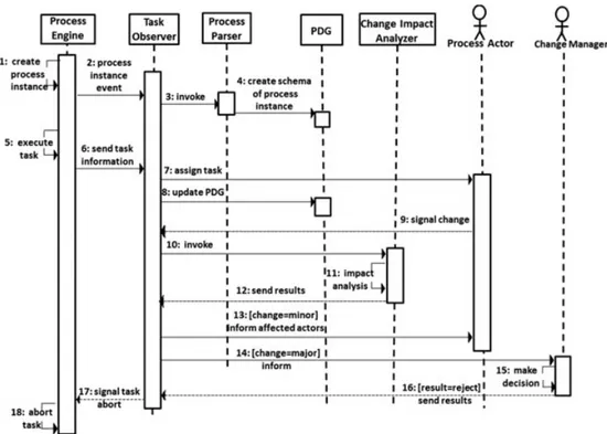
2. End User UIs: A set of user interfaces to allow process actors (i.e., system and process actors) to interact with the core PMS to request their task list, claim and complete the tasks assigned to them. The novelty here is a new interface offering process actors the possibility to send a change request during their task execution. Thanks to this new functionality, process actors can integrate emergent changes, which are not described in their process model, into the process execution. Also, a new role Change Manager together with the interface are defined to centralize the change requests and show the result of potential change impacts.
3. Process Parser: This sub-component constructs the structure of a new process instance and adds this structure to the PDG. It will be invoked by Task Observer when a new process instance is created.
4. Task Observer: This sub-component is responsible for controlling process actors’ tasks and keeping the PDG updated with the run-time events happening during task’s life cycle. Besides the standard human task events defined by the WS-HT specification [8], we defined a new event Change Request and the corresponding handler to capture change requests sent asynchronously by process actors. When receiving a change request signal, Task Observer invokes the Change Impact Analyzer.
5. Change Impact Analyzer: When the Change Manager receives a change request, he can use this component for traversing the PDG and extracting the elements potentially affected by the change request. The result of the change impact analysis is an Impact Graph (IG) that gives some information to help the change manager on the change implementation decision and in informing the concerned elements in a timely manner.
In the next sections, we present the functionalities of the three sub-components Process Parser, Task Observer, and Change Impact Analyzer.
4.2.1. Process parser. This component is responsible for extracting from a process model the process information at schema level in order to construct the structure of the PDG.
Whenever a process engine creates a new process instance from a process model, the Task Observer invokes the parser to analyze the given process model and create a corresponding graph structure in PDG. For each activity in the process model, we extract its input output work products as well as identify the performing actors and resources needed for the task. Then the parser creates the corresponding PDG nodes representing these process elements and the PDG edges representing the relations between them. By default the parser handles an activity as a single-instance task. For multi-instances activities, their task instances will be created dynamically in PDG when the number of instances is known during the process execution. Afterwards, the PDG will be updated with run-time information by the Task Observer as the process execution progresses.
4.2.2. Task observer. The main role of Task Observer is keeping the PDG updated with the system state maintained by the process engine. Thus, it provides a sound basis for change impact analysis. To do so, Task Observer listens to run-time events happening in the system via the interaction with the process engine and process actors. Then it proposes the appropriate handlers for updating the PDG according to the occurring event.
We classify different events relating to any changes at run-time environment into three categories: 1. Process Instance Event: It concerns the events of creating orfinishing (or aborting) a process instance. The event handler of this event type modifies the structure of the PDG: adding to the PDG the new nodes of the created process instance or deletes all nodes of finished process
instance inside the PDG. Constructing of the schema of a new process instance is realized by the Process Parser sub-component.
2. Task Life cycle Event: All events concerning the operations specified by WS-HT for human tasks [8] are regrouped in this category: claiming, releasing, completing, or aborting a task. The basic Task Management Component of the core PMS is responsible for these operations and, via different event handlers corresponding to a specific event, informs the process engine of the progression of the process instance execution. Using Task Observer as our own task service, we extended the basic event handlers for the above events to update correctly the PDG in each specific situation so that the PDG always represents the run-time state of the process instances.
• When a process actor claims (or releases) a task, the states of the involved PDG nodes (i.e., claiming actor node, claimed task node) are updated and a PDG perform edge between these two nodes is created (or deleted). We supposed that PDG actor nodes are created from the list of process actors taken from the Resource Repository. • Basically, whenever a process actor completes or aborts a task, the state of the
corre-sponding PDG task node and its related nodes (performing actor and produced work product) will be updated. If the subsequent task is multi instance, the update of the PDG becomes more complicated.
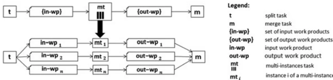
There are many patterns describing situations where there are multiple threads of execution active in a process model. In this work, we focus on the pattern Multiple Instances with a priori Run time Knowledge [9] concerning the creation of multiple instances of a task within a process instance. The number of task instances depends on run-time factors, often the input data of the task. The task instances run concurrently and will be synchronized before triggering the subsequent task. Inspired from the pattern To Multiple Instance Task Instance specific data passed by value [9], we update the PDG based on the passing data elements from a single-instance task to a multi-single-instance task as shown in Figure 4.
In this pattern, the output set in wp of the current task t is the input of a multi instance task mt. In such a case, when the current task t is completed, the cardinality n of its output set in wp determines the number of task instances of the subsequent task mt. For updating the PDG, the sub-graph from set in wp to mt will be duplicated n times. In each sub-graph the set work product node in wp is replaced with an item in wpiin the set; the task node mt takes the
run-time id of its task instance. If mt is a multi-instance process, all nodes inside the sub-process will be duplicated. At the conclusion of mt, n instances mtiwill be connected to the
merge task m in the PDG.Our example and discussion respectively presented in Figure 1 and Section 2.1 illustrate this special situation with the work product {Component Requirements}, which is the input of the multi-instance sub-process Component Development Process.
3. Change Request Event: This is a new event that we defined to allow process actors to send a change request at any moment when executing a task. Here we handle the run-time unofficial changes that cannot be previously foreseen and modeled in the process model. Changes can concern modifications on the process actor’s work products, working time or resources required for his work. We defined a new task handler to allow the action sending change request from the process actors working environment. On the other side, the Task Observer handler is responsible
4.2.3. Change impact analyzer. When the Task Observer receives the change request CR, it invokes the Change Impact Analyzer to analyze the impact of the change described in the CR.
In a change request CR (changeInitiator, changedElement, changedType): • changeInitiator is the process actor who initiates the change.
• changedElement is the element that he wants to modify. The changedElement must be one of the elements related to the changeInitiator’s current task.
• changeType is the type of change that the changeInitiator wants to make. He can make minor changes for correcting small problems of a work product without causing reworking in other tasks. If he wants to evolve a work product whose changed content can result in reworking on other tasks, he has to make his change as major changes.
The Change Impact Analyzer carries out the impact analysis by traversing the PDG from the changed element thorough possible types of edges. The traversal can be conducted in backward or/and forward mode according to a specific type of change as presented in the Section 5. The result of the traversal is a digraph so-called Impact Graph (IG), which is an extraction of the global PDG but contains only the process elements impacted by the change. These elements are detected by the emerging dependencies among run-time process elements in the PDG based on shared data, resources or temporal sequences. The obtained IG is considered as the base to conduct impact analysis at different levels according to a specific need of change manager.
The impact can be direct if an element works with the changed element or indirect if an element works with an element impacted (directly or indirectly) by the change. Moreover, thanks to the PDG that keeps trace of all elements in the development, we can have a thorough analysis on different axes: by examining both nodes inside and outside of the changeInitiator’s process instances, we can identify the impacts on the elements in the scope of a project or in other projects; by examining all existing task nodes completed, current and future we can know which elements are really impacted or potentially impacted.
We can go further in such analysis by annotating the nodes of the IG with some interesting metrics such as resource costs or work product completion percentages. For instance, regarding any affected work product the percentage of its completion at the time of change can be estimated based on the duration of the task that produces it. This feature, which is dependent on a specific given domain for calculating the required metrics, is not presented in this paper but in our previous work [10].
We summarize the whole procedure of the Change Aware Process Environment in the Figure 5.
5. VALIDATION STUDY
This section presents the prototype CAPE developed to validate our proposal. First, we describe the implementation of CAPE. Second, we report the use of CAPE for a case study and the feedback of our industrial partners.
5.1. Prototype implementation
As described in Section 2, our key goal is to coordinate better process actors at the moment of change. To this aim, our prototype provides the functionalities that allows process actors to signal a change and inform concerned people. As presented in Section 4, we distinguish two types of changes: minor changes for correcting small problems of a work product without causing reworking and major changes for evolving a work product with possible reworking. CAPE can analyze the change impact of both.
This section presents our strategy to implement the two components of CAPE: PMS and Change Management Component that allow creating and updating the PDG as a basis of change analysis.
to catch the sent change request and then invoke the Change Impact Analyzer sub-component to extract from the PDG the elements potentially affected by the requested change.
• Usage of jBPM as a basic PMS: Our idea is to enrich an existing PMS with a change management mechanism and not develop a new PMS from scratch. First, we looked for PMSs supporting the Software and Systems Process Engineering meta modeling language (SPEM) [11]. However, to our knowledge, there are not mature and extensible process environment executing SPEM processes except some academic works as [12, 13] and the commercial tool IBM Rational Team Concert [14]. Thus, we turned to existing operational Business Process Management Systems that can be used to execute SPEM processes that are mapped to a executable business process language. Based on the features of existing BPMSs, we chose jBPM [15], a flexible, light-weight, fully open-source and extensible BPMS, for developing our PMS component. Like other BPMS, jBPM is composed of several components that each one resolves a particular function inside the BPMS architecture as shown in Figure 3a. jBPM proposed a basic Human Task Processor, a back-end task service that manages the life cycle of tasks realized by human users, based on the WS-HT standard specification [8]. To assist process actors on managing run-time changes, we used jBPM APIs (WorkItemHandler class) for re-implementing this task service as our Change Management Component that enhances the basic Human Task Processor with new functionalities on change notifying and analyzing. Thus, as part of the prototype, new user interfaces are developed to handle process actors’ tasks in a task-list-oriented way.
• Usage of Neo4j as a graph database to store PDG: The PDG describing the running processes of an organization can be huge. Thus, in order to store and manipulate efficiently the PDG, we explored the use of NoSQL data management system, in particular on systems proposing native graph data management. A graph database is typically substantially faster for connected data sets and uses a schema-less, bottoms-up model that is ideal for capturing ad hoc and rapidly changing data [16]. To this aim, Neo4j [17], an object oriented and open-source graph database, has been chosen. Neo4j allows us to store and query the PDG in an efficient way thanks to its advantages on powerful traversal framework and the declarative graph query language Cypher. We used the Neo4j Core-Java-API to develop a Neo4j embedded application in our Change Impact Analyzer. Thus, we can benefit not only an object-oriented approach to manipulate the graph database, but also highly customizable high-speed traversal- and graph-algorithm implementations.
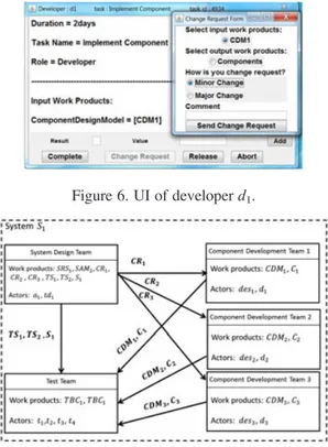
When facing a problem that necessitates a change, process actors evaluate the importance of the change and select the way to handle it with the help of CAPE. Figure 6 shows an example of the task user interface in CAPE for developer d1when he detects a minor problem on the work product
CDM1and sends the change request. By choosing minor change,first CAPE helps the process actor
to inform the change management component as well as the actors concerning to the changed work product, especially if it’s responsible. Then he can continue performing his task after making the change. By choosing major change, first the process actor sends a change request to the change manager in order to analyze the change impact and make a decision. If the change is accepted, then the change manager informs affected actors and then the change initiator can carry out his task. If the change is refused, the process engine aborts the initiator’s task.
5.2. Experiments
The experiment presented in this paper is a simplified version of a real case study conducted in the context of the project FUI2Agile tools for Conception and Validation of Systems (ACOVAS). We focus on the system integration phase where changes occur with high rates. To evaluate CAPE, we simulated the execution of the processes described in Figure 1 for three projects, using the same setup for project1as presented in Table I (cf. Section 2). Figure 7 gives the organizational model of
project1and focuses on the elements concerned by change scenarios. In this project, the system is
composed of three components C1, C2, C3 developed by three different teams. The system
integration and the integration tests are carried out respectively by the system team and the test team. The development teams can be intern of a company or belong to different suppliers that can be geographically dispersed in different sites.
CAPE can handle change situations conform to two change patterns correction and evolution described as follows:
5.2.1. Correction pattern. As illustrated in Figure 8, this pattern concerns a situation when a process actor faces a minor change during his task tsk2. To continue his task, he needs to change (correct) his
Figure 6. UI of developer d1.
2FUI a French academic industry research program.
input work product wp1, which is produced by the completed task tsk1. At the moment of change, task
tsk3and tsk5are in parallel with tsk2, and tsk4has not been started yet.
First, CAPE carries out a backward analysis to detect the completed elements concerned by the change that needs to be informed but does not need to rework on the changed element. Backward analysis is implemented by the traversing the PDG through the incoming data edge of changed element wp1 that results in tsk1. Second, CAPE runs a forward analysis to deduce the current or
future elements that can be concerned by the change. Forward analysis is implemented by recursively traversing the PDG through all outgoing edges of changed element. According to the pattern, based on the shared work product wp1, forward analysis gives us tsk3as an affected element
and wp2and tsk4as potential affected elements. The correction on the wp1can add delay time on
completing task tsk2. Consequently, all the tasks need ir (i.e., tsk5) will be impacted.
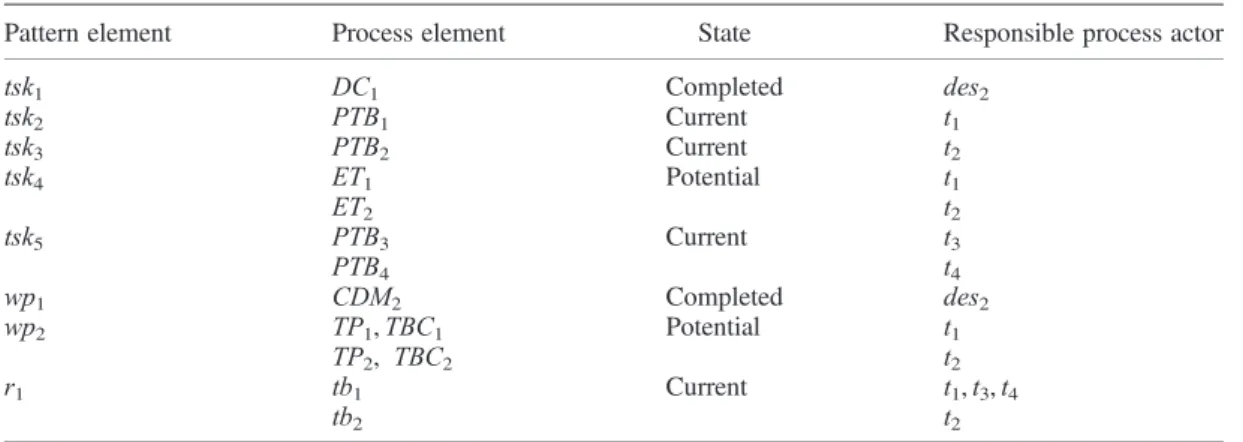
Table II shows one possible scenario based on the pattern in which the change happens in the project1 when the tester t1 faces a problem during his task Prepare TestBench to prepare the test
bench tb1. This problem requires a minor change on his input work product CDM2 (previously
produced by des2 in the task Design Model). At the moment of change, another tester t2 is using
CDM2to prepare the test bench tb2for another test, and the testers t3and t4are waiting for the test
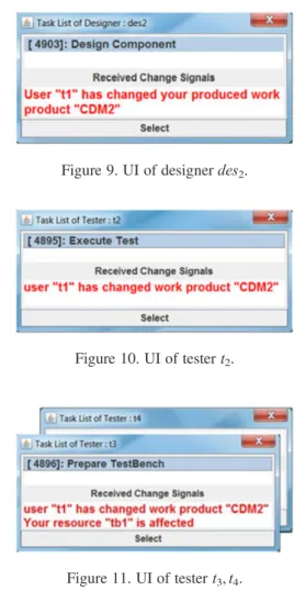
bench tb1 for their task respectively in project2 and project3. Figures 9 11 present the scenario
simulated in CAPE. We can see that the impacted actors inside the project1(i.e., des2and t2) as well
as outside the project1(i.e., t3and t4) are informed of the change.
5.2.2. Evolution pattern. The pattern in Figure 12 presents a situation when a major change (normally caused by the environment of the project) on the work product wp1(previously produced
Figure 8. Correction pattern.
Table II. Correction scenario.
Pattern element Process element State Responsible process actor
tsk1 DC1 Completed des2 tsk2 PTB1 Current t1 tsk3 PTB2 Current t2 tsk4 ET1 Potential t1 ET2 t2 tsk5 PTB3 Current t3 PTB4 t4 wp1 CDM2 Completed des2 wp2 TP1, TBC1 Potential t1 TP2, TBC2 t2 r1 tb1 Current t1, t3, t4 tb2 t2
by tsk1) is requested. The change necessitates creating a new task instance tsk′1to modify wp1. Such a
change can impact the subsequent tasks of tsk1, completed or current.
CAPE performs a forward analysis by traversing the PDG through outgoing data edges of changed element wp1to detect all the elements that are dependent on wp1. As shown in the Figure 12, this
analysis gives the list of impacted elements comprising the completed elements tsk2and wp4and the
current task tsk4. However, the rework on wp1 does not have any impacts on elements tsk2, wp2,
and wp3.
Normally, major changes require an in-depth analysis to better estimate the impact. Thus, it is important to identify the relevant and irrelevant elements to a change. This issue is especially demanding in the situation where the changed element is a workProductSet and it related to a multi-instance task whose number of multi-instances is only known at run-time. Concretely, if the type of wp1is
workProductSet and tsk2is a multiInstance task, the number of tsk2’s instances is determined by the
number of wp1’s elements. When reworking wp1, it may happen that only some of its elements are
modified. In this case, it would be useful to identify which instances of tsk2will be affected by the
changed elements in wp1.
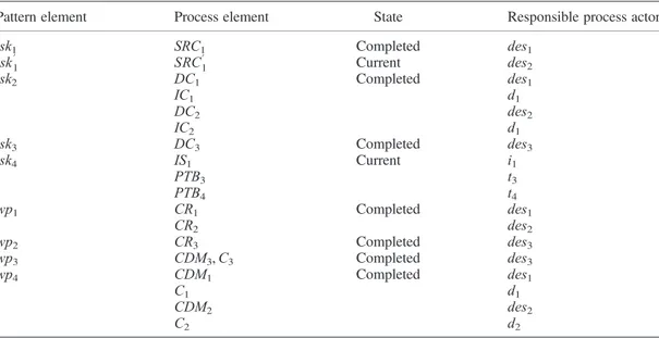
Table III shows one possible scenario of the pattern Evolution with emphasizing on the multi-instance elements. At the moment of change, all components C1, C2, and C3are implemented and
integrator i1 is performing the system integration (i.e., all precedent tasks of the task Integrate
System are completed). The change happens when the des2 needs to execute once again the task
Specify Component Requirements to modify the work products CR (previously completed). CR is a workProductSet and is the input of the multi-instance task DC. In this scenario, we suppose that only the elements CR1and CR2of CR which are the input respectively of the instance DC1and
DC2of the task DC are changed. Figure 13 show the impact analysis of this scenario that CAPE
Figure 9. UI of designer des2.
Figure 10. UI of tester t2.
gives the change manager for this major change. The impacted actors are distinguished by the cause of impact, while des1, des2, d1, d2, t1, t2, and i1 are affected by the change on their work products
concerning the components C1 and C2, t3 and t4 in other projects are affected by sharing the test
bench tb1with t1. We can see that the actors des3, d3, and t3who work on the component C3are
not affected.
5.3. Discussion
Our framework is based on the assumptions that a central graph database, a central resource repository, and an application server (e.g., jBOSS) are provided to support the change management in a distributed environment. However, because of the security policies of our industrial partners, currently, we could not deploy our prototype directly in their real development environment. So we conducted the validation with the participation of our partners on a simulated development environment on one
Figure 12. Evolution pattern.
Table III. Evolution scenario.
Pattern element Process element State Responsible process actor
tsk1 SRC1 Completed des1 tsk′1 SRC′1 Current des2 tsk2 DC1 Completed des1 IC1 d1 DC2 des2 IC2 d1 tsk3 DC3 Completed des3 tsk4 IS1 Current i1 PTB3 t3 PTB4 t4 wp1 CR1 Completed des1 CR2 des2 wp2 CR3 Completed des3 wp3 CDM3, C3 Completed des3 wp4 CDM1 Completed des1 C1 d1 CDM2 des2 C2 d2
central machine. However, the simulation does not affect the feasibility of our proposal because the main work is done on the PDG.
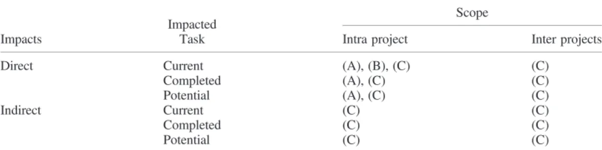
We summarize in Table IV different types of impacts that should be analyzed when a change occurs. Then we point out which types of impacts that can be identified in three solutions: (A) without supporting tools (like actual solution of our partners in project ACOVAS), (B) with run-time information taken from a standard process environment (as jBPM), and (C) with information taken from our change-aware process environment CAPE.
The Table IV shows the advantages of CAPE compared with the solutions (A) and (B) in analyzing inter-projects change impacts as well as impacts on tasks at different states. CAPE has this capability thanks to the PDG, which provides a view of the whole system and also the history of system processes’ execution. Another remark is that CAPE allows an immediate analysis and propagation of changes, whereas it takes more time in the solution (A) and (B). In (A), without supporting tools, changes propagation is done by human actors and often the change request has to be passed through many organizational levels so that its impact can be estimated. In (B), using only a standard process environment, impact analysis can be done by complex queries on various process logs, but lacking the information about the data and resources using by tasks, this analysis is rather limited.
The feedback of our partners on the preliminary results of CAPE is positive. They affirmed the needs of managing unofficial changes during the development process, especially for dealing with problems in the testing phase where time constrains are important, because physical and human resources are booked and allocated. Although additional works will be needed to develop a full solution that can be integrated to the real environment of our partners, they found that CAPE is helpful and motivated to continue working with us on the improvement of CAPE.
6. RELATED WORK
Change management can be tackled from different perspectives, such as process perspective, tool perspective, and product perspective [1, 3]. According to [3], tools and methods to support the change process can be divided into two groups: (1) those that help managing the workflow or
Figure 13. UI of change manager.
Table IV. Simulation results.
Impacts
Impacted Task
Scope
Intra project Inter projects
Direct Current (A), (B), (C) (C)
Completed (A), (C) (C)
Potential (A), (C) (C)
Indirect Current (C) (C)
Completed (C) (C)
documentation of the process and (2) those which support process actors in making decisions at a particular point in the engineering change process (e.g., the risk/impact analysis phase).
We use this structure to discuss some similar works on the tool perspective in Business Process, SSE communities.
Work flow/documentation support: Computer-based tools have been recognized as an essential to support engineering change [18]. In terms of academic works, Chen et al. [19] proposed a tool to support distributed engineering change management linking with concurrent engineering. Lee et al. [20] introduced a prototype for collaborative environment for engineering change management, which combines ontology-based representations of engineering cases, case-based reasoning for retrieval and a collaboration model. In the business process community, many of the existing works on change management focus on proposing mechanisms to enable process adaptation and changes propagation. Lanz et al. in [21] propose a tool to support process adaptation at run-time. Other researches [22, 23] have investigated solutions for process adaptation by allowing process actors to modify the process (e.g., add or delete a task). Reichert et al. in [24] conduct a good survey on the flexibility of workflow system in order to response better to changes. However, these studies apply the change without consideration of its impact and stay as prototypes, which are difficult to be validated for industries.
In the engineering domain, commercial tools such as IBM Rational Team Concert [14] and Siemens TeamCenter [25] provide the control for collaborative work. However, these tools in general are costly, very complex to use and to customize, thus few companies have adopted them in their environment. In the business process domain, many commercial tools have been developed, among them we cite the most interesting such as Bonita [26] and jBPM [15]. The positive point of these BPMSs is that they offer partial or full open-source API that enable extensions in staying with standardized and operational environments. Envisaging a validation of our prototype in software and system engineering, we need to keep this vision as standard and operational. That is why we developed our academic prototype based on jBPM.
Decision making support: A wide variety of techniques are used in the context of impact analysis and change propagation [18] in the engineering domain. There is currently no commercial package that helps predict the effect of a change; however, some work is being carried out in academic institutions [3]. Eckert et al. [1] based on a study conducted in Westland Helicopters, identified two types of changes: the emergent changes and the initiated changes. This particular study was based on the interviews conducted with the company’s employees. They proved that by capturing the design knowledge and experience (e.g., source of change, interdependencies between parts and systems, etc.), in the form of experienced designers in the company, an automatic tool to identify the engineering change propagation can be developed. This work has further led to the development of a computer support tool by Jarrat et al. [27] to identify the risk of a change. They apply the Change Prediction Method to realize how changes spread through a product by using the Design Structure Matrix as the basis of the product model. The tool uses a simple model of risk, where the likelihood of a change propagating is derived from the past experience in terms of their occurrence and the impact such changes would have. This technique has been used in many other works [28, 29]. Grantham-Lough et al. [30] applied prediction methods for change propagation and risk estimations based on the functional decomposition of the product in early design stages. Their methods utilize history of design failures and assume that the behavior of past products is sufficiently similar to current or new products. As a result, tools show a diversity of approaches but based on prediction approaches and using past experiences. Their applicability reduces in the real-time change analysis when real-time plays a major role in informing the change affected partners.
Impact analysis of change is also an important topic in the research area of business process domain. In [5], a change propagation approach called Refine Process Structure Tree is proposed to deal with change in process choreographies. This approach addresses both phases of process change but only inside one process instance. The approval of a change is done by negotiations among change initiator and affected partners. By contrast, our approach derives the impact of change inside and among process instances and also provides useful metrics in order to facilitate the negotiation phase. Muler in [22] dealt with logical failures management in inter-workflow collaboration scenarios and extends the previous work [31] by adding temporal and qualitative implications of workflow
adaptation. Temporal implications of an adaptation are determined by estimating the duration required to execute the dynamically adapted workflow and by comparing it with originally fixed time constraints. The metrics used in their approach are for deriving the essence of adaptation not for measuring the impact of the adaptation. Impact of change among process instances was not investigated as they considered only the impact of adaptation in one process instance.
7. CONCLUSIONS
To date, there is a gap between the process management and change management. No automation support for change management is one of the most popular causes of defects in multi-disciplinary engineering environments. Thus, as pointed out in [32], lack of integrated change management supports is one of the reasons of the limited acceptance of process environments in system and software industry. Combining the management of processes and changes to provide effective communication and synchronization through the system can decrease the cost of reworks [3].
Convinced by the aforementioned statement, we have developed a prototype of a change aware process environment that consolidates the process management and the change management into one development environment. In this environment, run-time changes which are not described in the process model can be integrated into process enactment. By providing process actors with the possibilities of notifying and analyzing changes, our environment allows them handle changes in a centralized and proactive way so that they can better anticipate and response to changes. Hence, we offer a process enactment more flexible but still controlled. A prototype, implemented in Java with the APIs of jBPM and Neo4j, is operational and is being validated with the case studies provided by our industry partners.
The key strength of this work is using run-time process information to establish hidden dependencies among processes, especially a process that supports multiple instances tasks and other processes in different projects. Those dependencies are invisible on the model level and only emerge at run-time via data exchanging or shared resources. By uncovering these dependencies, we could provide a more thorough and precise analysis on the impacts of changes. This advantage should be particularly helpful for System Engineering where the development involves often various teams in different domains and on extreme complex products. Thus, it is important to find out exactly the impacted elements among a huge set of process elements.
One weakness of this study was the limitation on the types of change request. We only dealt with the change concerning modification the content of a work product or the change on execution time or resource using time. Changes on process structure are not allowed at run-time. Another point that may limit the application of our approach is the strong assumption on the input process model. The current PMS requires a well-defined process model describing the activities of all process roles. This global model is needed for extracting the dependencies among process elements. However, in reality, it is hard to have such a process model.
To overcome the aforementioned deficiencies, we are working on a bottom-up approach for process modeling and enactment. The idea is letting each process actor describes his own work. Then, from separate process fragments, our PMS can construct progressively the PDG, use it to synchronize the activities of process actors, and also to construct the global process model.
ACKNOWLEDGEMENTS
Part of this research has been supported by the French research projects FUI ACOVAS and ANR InnoServ (Innovation de Services pour personnes fragiles). We are grateful to our industrial partners in ACOVAS project who have helped us on developing the case studies for our research and on validating our prototype.
REFERENCES
1. Eckert C, Clarkson P, Zanker W. Change and customisation in complex engineering domains. Research in Engineering Design March 2004;15(1):1 21.
2. MutschlerB, Reichert M, Bumiller J. Unleashing the effectiveness of process oriented information systems: problem analysis, critical success factors, and implications. Systems, Man, and Cybernetics, Part C: Applications and Reviews, IEEE Transactions on May 2008;38(3):280 291. DOI:10.1109/TSMCC.2008.919197.
3. JarrettTAW, Eckert CM, Caldwell NHM, Clarkson PJ. Engineering change: an overview and perspective on the lit erature. Research in Engineering Design 2011;22(2):103 124.
4. HajmoosaeiM, Tran HN, Percebois C, Front A, Roncancio C. Towards a change aware process environment for sys tem and software process. Proceedings of the 2015 International Conference on Software and System Process, ICSSP 2015, Tallinn, Estonia, August 24 26, 2015; 32 41.
5. FdhilaW, Indiono C, Rinderle Ma S, Reichert M. Dealing with change in process choreographies: design and imple mentation of propagation algorithms. Information Systems 2015;49:1 24.
6. GuptaC, Singh Y, Chauhan DS. Dependency based process model for impact analysis: a requirement engineering perspective. International Journal of Computer Applications 2010;6(6):28 30.
7. BarghoutiNS, Emmerich W, Schfer W, Skarra A. Information management in process centered software engineering environments. In A. Fugetta and A. Wolf, editors, Software Process Trends in Software. Wiley: New York, 1996; 53 87. 8. OASIS. Web Services Human Task (WS HumanTask) Specification Version 1.1 August 2010. URL http://docs.oa
sis open.org/bpel4people/ws humantask 1.1.html.
9. van der AalstWMP. Workflow patterns. URLhttp://www.workflowpatterns.com.
10. HajmoosaeiM, Tran HN, Percebois C, Front A, Roncancio C. Impact analysis of process change at run time. Proceedings of The 24th IEEE International Conference on Enabling Technologies: Infrastructure for Collaborative Enterprises (to be appeared), WETICE 2015, 2015.
11. (OMG) OMG. Software Process Engineering Metamodel (SPEM) 2007. URL http://www.omg.org/spec/SPEM/2.0/. 12. BendraouR, Combemale B, Cregut X, Gervais MP. Definition of an executable spem 2.0. Proceedings of the 14th Asia Pacific Software Engineering Conference, APSEC ’07, IEEE Computer Society: Washington, DC, USA, 2007; 390 397. DOI:10.1109/APSEC.2007.38
13. PortelaC, Vasconcelos A, Oliveira S, Silva AA, Elder S. Spider pe: a set of support tools to software process enactment. Proceedings of the 9th International Conference on Software Engineering Advances, ICSEA’14, 2014. 14. IBM. Rational team concert. URL http://www.ibm.com/developerworks/downloads/r/rtc/.
15. JBoss. jbpm. URL http://www.jbpm.org/.
16. RobinsonI, Webber J, Eifrem E. Graph Databases. O’Reilly Media, Inc, 2013. 17. Neo4j. URL http://www.neo4j.com.
18. HuangG, Mak K. Computer aids for engineering change control. Journal of Materials Processing Technology 1998; 76:187 191. DOI:10.1016/S0924 0136(97)00347 6.
19. Chen YM, Shir WS, Shen CY. Distributed engineering change management for allied concurrent engineering. International Journal of Computer Integrated Manufacturing 2002;15(2):127 151.
20. LeeHJ, Ahn HJ, Kim JW, Park SJ. Capturing and reusing knowledge in engineering change management: a case of automobile development. Information Systems Frontiers 2006;8(5):375 394.
21. AristaFlow. URL http://www.aristaflow.com/.
22. MullerR, Rahm E. Dealing with logical failures for collaborating workflows. CoopIS, Lecture Notes in Computer Science, vol.1901 Etzion O, Scheuermann P (eds.). Springer: Berlin, Heidelberg, 2000; 210 223.
23. MinorM, Bergmann R, Görg S, Walter K. Towards case based adaptation of workflows. Proceedings of the 18th International Conference on Case Based Reasoning Research and Development, ICCBR’10. Springer Verlag: Berlin, Heidelberg, 2010; 421 435. DOI:10.1007/978 3 642 14274 1 31
24. Reichert M, Weber B. Enabling Flexibility in Process Aware Information Systems Challenges, Methods, Technologies. Springer: Berlin Heidelberg, 2012.
25. Siemens. Teamcenter. URL http://www.plm.automation.siemens.com/. 26. BonitaSoftware. URL http://www.bonitasoft.com/.
27. JarrattTAW, Eckert CM, Clarkson PJ, Schwankl L. Product architecture and the propagation of engineering change. 7th International Design Conference (Design 2002), 2002; 75 80.
28. OhS, Park B, Park S, Hong YS. Design of change absorbing system architecture for the design of robust products and services. HCI (4), Lecture Notes in Computer Science, vol.4553 Jacko JA (ed.). Springer, 2007; 1110 1119. 29. KöNigsSF, Beier G, Figge A, Stark R. Traceability in systems engineering review of industrial practices, state of
the art technologies and new research solutions. Advanced Engineering Informatics 2012;26(4):924 940. 30. Grantham LoughKTI, Stone MC. Prescribing and implementing the risk in early design (red) method. ASME2006
design engineering technical conferences CDROM. American Society of Mechanical Engineers (ASME): Philadelphia, Pennsylvania, USA, 2006.
31. MullerR, Greiner U, Rahm E. Agent work: a workflow system supporting rule based workflow adaptation. Data Knowledge Engineering 2002; 223 256.
32. MatinnejadR, Ramsin R. An analytical review of process centered software engineering environments. IEEE 19th International Conference and Workshops on Engineering of Computer Based Systems, ECBS 2012, Novi Sad, Serbia, April 11 13,2012, 2012; 64 73. DOI:10.1109/ECBS.2012.11