En vue de l'obtention du
DOCTORAT DE L'UNIVERSITÉ DE TOULOUSE
Délivré par :
Institut National Polytechnique de Toulouse (INP Toulouse)
Discipline ou spécialité :
Sureté de Logiciel et Calcul à Haute Performance
Présentée et soutenue par :
M. ARNAUD DIEUMEGARD le vendredi 30 janvier 2015
Titre :
Unité de recherche : Ecole doctorale :
FORMAL GUARANTEES FOR SAFETY CRITICAL CODE GENERATION:
THE CASE OF HIGHLY VARIABLE LANGUAGES
Mathématiques, Informatique, Télécommunications de Toulouse (MITT)
Institut de Recherche en Informatique de Toulouse (I.R.I.T.)
Directeur(s) de Thèse :
M. YAMINE AIT AMEUR M. MARC PANTEL
Rapporteurs :
M. CLAUDE MARCHE, UNIVERSITE PARIS 11 M. RICHARD PAIGE, UNIVERSITY OF YORK
Membre(s) du jury :
1 M. PHILIPPE LAHIRE, UNIVERSITE DE NICE SOPHIA ANTIPOLIS, Président
2 M. MARC PANTEL, INP TOULOUSE, Membre
2 Mme VIRGINIE WIELS, ONERA TOULOUSE, Membre
2 M. PAUL GIBSON, TELECOM SUD PARIS, Membre
Abstract
Control and command softwares play a key role in safety-critical embedded systems used for human related activities such as transportation, healthcare or energy. Their impact on safety makes the assessment of their correctness the central point in their development activities. Such systems verification activities are usually conducted according to normative certification guidelines providing objectives to be reached in order to ensure development process reliability and thus prevent flaws. Verification activities usually relies on tests and proof reading of the software but recent versions of certification guidelines are taking into account the deployment of new development paradigms such as model-based development, and formal methods; or the use of tools in assistance of the development processes.
Automatic code generators are used in most safety-critical embedded systems development in order to avoid human related software production errors and to ensure the respect of development quality stan-dards. As these tools are supposed to replace humans in the software code production activities, errors in these tools may result in embedded software flaws. It is thus in turn mandatory to ensure the same level of correctness for the tool itself than for the expected produced code. Tools verification shall be done accord-ing to qualification guidelines. We advocate in our work the use of model-based development and formal methods for the development of these tools in order to reach a higher quality level.
Critical control and command software are mostly designed using graphical dataflow languages. These languages are used to express complex systems relying on atomic operations embedded in blocks that are gathered in block libraries. Blocks may be sophisticated pieces of software with highly variable structure and semantics. This variability is dependent on the values of the block parameters and of the block’s context of use.
In our work, we focus on the formal specification and verification of such block based languages. We experimented various techniques in order to ensure a formal, sound, verifiable and usable specification for blocks. We developed a domain specific formal model-based language specifically tailored for the specifi-cation of structure and semantics of blocks. This specifispecifi-cation language is inspired from software product line concepts in order to ensure a correct and scalable management of the blocks variability. We have ap-plied this specification and verification approach on chosen block examples from common industrial use cases and we have validated it on tool prototypes.
Blocks are the core elements of the input language of automatic code generators used for control and command systems development. We show how our blocks formal specification can be translated as code annotations in order to ease and automate the generated code verification. Code annotations are veri-fied using specialised static code analysis tools. Relying on synchronous observers to express high level requirements at the input model level, we show how formal block specification can also be used for the translation of high level requirements as verifiable code annotations discharged using the same specialised tooling. We finally target the assistance of code generation tools qualification activities by arguing on the ability to automatically generate qualification data such as requirements, tests or simulation results for the verification and development of automatic code generators from the formal block specification.
Resumé
Les fonctions de commande et de contrôle sont parmi les plus importantes des systèmes embarqués critiques utilisés dans des activités telles les transports, la santé ou la gestion de l’énergie. Leur impact potentiel sur la sûreté de fonctionnement fait de la vérification de leur correction l’un des points les plus critiques de leur développement. Cette vérification est usuellement effectuée en accord avec les normes de certification décrivant un ensemble d’objectifs à atteindre afin d’assurer un haut niveau de qualité du système et donc de prévenir l’apparition de défauts. Cette vérification du logiciel est traditionnellement basée sur de nombreux tests et des activitiés de relectures de code, toutefois les versions les plus récentes des standards de certification permettent l’utilisation de nouvelles approches de développement telles que l’ingénierie dirigée par les modèles et les méthodes formelles ainsi que l’utilisation d’outil pour assister les processus de développement.
Les outils de génération automatique de code sont exploités dans la plupart des processus de développe-ment de systèmes embarqués critiques afin d’éviter des erreurs de programmation liées à l’humain et pour assurer le respect des règles de production de code. Ces outils ayant pour vocation de remplacer les hu-mains pour la production de code, des erreurs dans leur conception peuvent causer l’apparition d’erreurs dans le code généré. Il est donc nécessaire de vérifier que le niveau de qualité de l’outil est le même que celui du code produit en s’assurant que les objectifs spécifiées dans les normes de qualification sont cou-verts. Nos travaux visent à exploiter l’ingénierie dirigée par les modèles et les méthodes formelles pour développer ces outils et ainsi atteindre un niveau de qualité plus élevé que les approches traditionnelles.
Les fonctions critiques de commande et de contrôle sont en grande partie conçues à l’aide de langages graphiques à flot de données. Ces langages sont utilisés pour modéliser des systèmes complexes à l’aide de blocs élémentaires groupés dans des librairies de blocs. Un bloc peut être un objet logiciel sophistiqué exposant une haute variabilité tant structurelle que sémantique. Cette variabilité est à la fois liée aux valeurs des paramètres du bloc ainsi qu’à son contexte d’utilisation.
Dans notre travail, nous concentrons notre attention en premier lieu sur la spécification formelle de ces blocs ainsi que sur la vérification de ces spécifications. Nous avons évalué plusieurs approches et tech-niques dans le but d’assurer une spécification formelle, structurellement cohérente, vérifiable et réutilisable des blocs. Nous avons finalement conçu un langage basé sur l’ingénierie dirigées par les modèles dédié à cette tâche. Ce langage s’inspire des approches des lignes de produit logiciel afin d’assurer une gestion de la variabilité des blocs à la fois correcte et assurant un passage à l’échelle. Nous avons appliqué cette ap-proche et la vérification associée sur quelques exemples choisis de blocs issus d’applications industrielles et l’avons validé sur des prototypes logiciels que nous avons développé.
Les blocs sont les principaux éléments des langages d’entrée utilisés pour la génération automatique de logiciels de commande et de contrôle. Nous montrons comment les spécifications formelles de blocs peu-vent être transformées en des annotations de code afin de simplifier et d’automatiser la vérification du code généré. Les annotations de code sont vérifiées par la suite à l’aide d’outils spécialisés d’analyse statique de code. En utilisant des observateur synchrones pour exprimer des exigences de haut niveau sur les modèles en entrée du générateur, nous montrons comment la spécification formelle de blocs peut être utilisée pour la génération d’annotations de code et par la suite pour la vérification automatique des exigences. Finale-ment, nous montrons dans quelle mesure les spécifications de blocs permettent de générer des données de qualification tel que des exigences, des tests ou des données de simulation utilisées pour la vérification et le développement de générateurs automatiques de code.
Table of Contents
Contents 9
List of Figures 12
List of Tables 13
1 Introduction 1
1.1 Embedded critical software . . . 1
1.2 Software verification and validation . . . 2
1.3 Model Driven Engineering and Formal Methods . . . 2
1.4 Automatic code generation . . . 3
1.5 The Simulink use case . . . 3
1.6 Research objectives . . . 3
1.7 Contributions . . . 4
1.8 Plan . . . 5
I Critical embedded systems design and implementation 7 2 Industrial context 9 2.1 Certification/Qualification . . . 9
2.1.1 Terminology . . . 9
2.1.2 DO-178B– Software Considerations in Airborne Systems and Equipment Certifi-cation . . . 10
2.1.3 DO-178C– Software Considerations in Airborne Systems and Equipment Certifi-cation . . . 10
2.1.4 DO-330– Software Tool Qualification Considerations Companion . . . 11
2.1.5 DO-331– Model-Based Development and Verification Supplement . . . 12
2.1.6 DO-332– Object-Oriented Technology and Related Techniques Supplement . . . . 13
2.1.7 DO-333– Formal Methods Supplement . . . 13
2.2 The need for domain specific languages . . . 14
2.2.1 From DSML to embeddable software through automatic code generation . . . 14
2.3 Our local research contributions to the ACG development field . . . 15
2.3.1 The GeneAuto ACG example . . . 15
2.3.2 The Projet-P/Hi-MoCo approach . . . 17
2.3.3 Other research contributions to the ACG development field . . . 18
2.4 Synthesis . . . 19
3 Languages formal specification - State of the art 21 3.1 Preliminary definitions . . . 21
3.1.1 Language . . . 21
3.1.2 Formal . . . 23
TABLE OF CONTENTS
3.1.4 Variable . . . 23
3.1.5 Highly variable language . . . 23
3.2 Model Driven Engineering . . . 24
3.2.1 Definition . . . 24
3.2.2 Use . . . 24
3.2.3 State of the art frameworks and languages . . . 24
3.2.4 Software product line engineering . . . 26
3.3 Software formal verification . . . 28
3.3.1 Static analysis of source code . . . 28
3.3.2 Deductive verification . . . 30
3.3.3 The Why3 platform . . . 31
3.4 Domain analysis: languages variability . . . 32
3.4.1 Languages variability examples . . . 33
3.4.2 Language variability analysis . . . 34
3.5 Synthesis . . . 36
4 Dataflow languages 37 4.1 Dataflow languages . . . 37
4.1.1 Origins . . . 37
4.1.2 Dataflow languages for critical systems development . . . 38
4.1.3 Synchronous dataflow languages . . . 38
4.1.4 Realistic implementation of KPN . . . 38
4.1.5 Dataflow model execution . . . 38
4.2 Dataflow model structure . . . 40
4.2.1 Graphical dataflow model structure . . . 41
4.2.2 Dataflow languages . . . 43
4.3 Well founded dataflow model . . . 44
4.3.1 Causality errors . . . 44
4.3.2 Data type overflow . . . 45
4.4 Dataflow languages block semantics variability . . . 45
4.5 Challenges to tackle regarding specification . . . 46
II Highly variable languages formal specification 47 5 Experiments with classic software engineering tools 49 5.1 Block specification requirements . . . 49
5.2 Block examples . . . 50
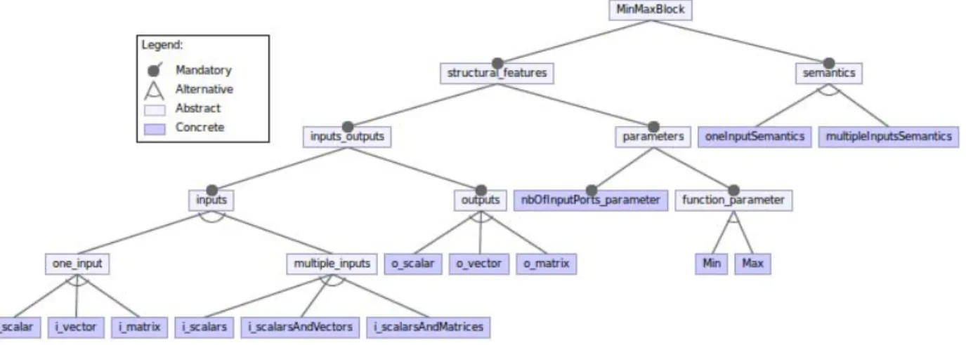
5.2.1 MinMax block . . . 50
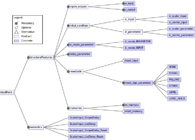
5.2.2 Delay block specification . . . 53
5.3 Mathematical notation for the specification of blocks . . . 54
5.4 UML for the specification of blocks . . . 56
5.4.1 UML block specification harness . . . 57
5.4.2 Injecting variability into UML . . . 61
5.4.3 Profiled UML + OCL specification for MinMax block . . . 63
5.4.4 Profiled UML + OCL specification for Delay block . . . 70
5.4.5 Choices made regarding UML modeling . . . 73
5.4.6 Limitations of the UML + profile + OCL specification approach . . . 73
5.5 SPLE for the specification of blocks . . . 73
5.5.1 SPLE specification approach . . . 74
TABLE OF CONTENTS
5.5.3 SPLE specification of the Delay block . . . 76
5.5.4 Limitation of the SPLE specification approach . . . 78
5.6 Two complementary approaches . . . 79
5.6.1 Methodology proposal . . . 79
5.6.2 From SPLE analysis to UML model . . . 79
5.6.3 Limitations of the methodology . . . 80
5.7 Synthesis . . . 81
6 A Domain Specific and Product Line experiment for language specification 83 6.1 Domain analysis . . . 83
6.1.1 Domain of study . . . 83
6.1.2 Variability modeling . . . 84
6.2 The BlockLibrary DSML . . . 84
6.2.1 Delay block interfaces specification . . . 84
6.2.2 Delay block textual specification . . . 87
6.2.3 BlockLibrary metamodel abstract elements . . . 87
6.2.4 Annotations . . . 89
6.2.5 Data types specification . . . 91
6.2.6 Block structural features . . . 92
6.2.7 BlockLibrary metamodel variability structure . . . 94
6.2.8 BlockLibrary metamodel specification containers . . . 98
6.3 Relation to feature modeling . . . 99
6.3.1 Conversion of a BlockType to a feature model . . . 99
6.3.2 Automatic feature model analysis . . . 100
6.4 From block specification to configurations . . . 101
6.4.1 Preliminary operations definitions on BlockLibrary elements . . . 101
6.4.2 Configuration and Signature constructs . . . 102
6.4.3 Operations based on Signature constructs . . . 104
6.4.4 Extraction of Signature elements . . . 105
6.4.5 Extraction of Configuration elements . . . 105
6.5 Semantics modeling . . . 107
6.5.1 Block semantics phases contracts . . . 108
6.5.2 Block semantics contract encoding with dynamic behaviors . . . 109
6.6 Specification verification properties . . . 111
6.6.1 Well-formedness . . . 111
6.6.2 Variability coverage . . . 111
7 BlockLibrary specifications formal verification 113 7.1 Verification prerequisites . . . 113
7.1.1 OCL specification . . . 114
7.1.2 BAL specification . . . 114
7.1.3 Why3 platform . . . 115
7.1.4 Transformation technology choice . . . 115
7.2 BlockLibrary specification example . . . 116
7.3 Why3 libraries . . . 116
7.3.1 Primitive data types theory . . . 116
7.3.2 BlockLibrary StructuralFeature theory . . . 119
7.4 OCL expressions transformation . . . 123
7.4.1 OCL standard library operations . . . 124
7.4.2 Collection operations . . . 125
TABLE OF CONTENTS
7.4.4 Value extraction iteration operations . . . 127
7.5 The BAL expressions transformations . . . 130
7.6 BlockLibrary verification transformations . . . 131
7.6.1 Variability verification transformation . . . 131
7.6.2 Semantics verification transformation . . . 135
7.7 Variability verification through SMT solving . . . 135
7.7.1 Specification extract variability verification . . . 136
7.7.2 Entire specification verification . . . 137
7.7.3 Goals transformation as a mean to ease the verification . . . 137
7.8 Semantics verification through SMT solving . . . 140
7.8.1 Hoare triple verification . . . 140
7.8.2 Adding loop invariants for the verification . . . 141
7.8.3 Automatic generation of invariants . . . 142
7.9 Scalability . . . 142
7.10 Limitations . . . 143
7.10.1 Dataflow languages capabilities limitations . . . 143
7.10.2 OCL and BAL Expressiveness limitation . . . 143
7.10.3 BlockLibrary limitations . . . 143
7.11 Synthesis . . . 143
III Automatic code generation verification based on the block library specification 145 8 Verification of generated code 147 8.1 Annotations for code verification . . . 147
8.1.1 Configuration matching of block . . . 147
8.1.2 Annotation generation . . . 148
8.1.3 Annotation verification . . . 152
8.1.4 Tool support . . . 152
8.2 Formal verification . . . 154
8.2.1 Synchronous observers . . . 155
8.2.2 Concrete application on the Counter system . . . 155
8.2.3 Logical expression extraction . . . 158
8.2.4 Main module generation . . . 160
8.2.5 From specific kind of properties to annotations . . . 161
8.2.6 A parallel work based on SO . . . 161
8.3 Gain wrt classical verification activities . . . 162
8.3.1 A complement to state of the art design verification . . . 162
8.3.2 Current limitations and perspectives . . . 162
9 Certification/Qualification data generation 163 9.1 BlockLibrary for qualification . . . 163
9.1.1 DO-331: Model-based technology . . . 164
9.1.2 DO-333: Formal methods . . . 164
9.2 BlockLibrary use for the certification of an ACG tool . . . 165
9.2.1 Providing unambiguous expression of requirements and architecture . . . 165
9.2.2 Supporting the use of automatically generated code . . . 167
9.2.3 Supporting the use of analysis tools for verification of requirements and architecture. 167 9.2.4 Supporting the use of simulation for partial verification of requirements, architec-ture, and/or Executable Object Code. . . 167
TABLE OF CONTENTS
9.3 Additional required verifications . . . 169
10 Conclusion & Future work 171 10.1 Research objectives fulfillment . . . 171
10.1.1 Research objective 1: Formal specification and verification of highly variable lan-guages . . . 171
10.1.2 Research objective 2: Uses of highly variable language formal specification for au-tomated generated code verification . . . 172
10.1.3 Research objective 3: Uses of highly variable language formal specification for ACG qualification . . . 172
10.2 Concrete productions . . . 173
10.3 Future research directions . . . 173
10.3.1 BlockLibrary-related activities . . . 173
10.3.2 Overall approach future works . . . 175
Appendices 177 A Complete block specifications 179 A.1 Delay block specifiation . . . 179
A.2 MinMax block specification . . . 189
B OCL grammar 193 C BAL grammar 199 D Why3 libraries 203 D.1 Why3 data types theories . . . 203
D.1.1 Numeric data types definition theories . . . 203
D.1.2 Common functions definition theories . . . 208
D.1.3 String data types definition theories . . . 208
D.2 BlockLibrary StructuralFeature definition theory . . . 212
D.3 Generic functions definitions and general purpose lemmas . . . 214
D.4 OCL language operations definitions . . . 216
D.5 OCL iteration operations definitions . . . 227
E ACSL verification using Frama-C 233
List of Figures
1.1 Code generation verification strategy . . . 5
2.2 GeneAuto toolkit architecture . . . 16
2.4 Projet-P toolkit architecture . . . 19
3.1 Space probe system Feature Model . . . 26
4.2 MultiRate dataflow model, boolean clock flow and block activation . . . 39
4.5 Metamodel for dataflow models . . . 42
4.6 GeneAuto DataTypes metamodel . . . 43
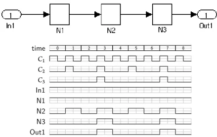
4.7 Simulink model for a modulo 3 counter . . . 44
4.8 A causality error example in a Simulink model . . . 45
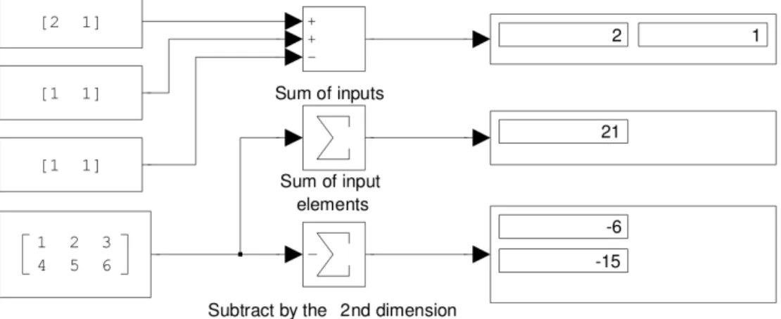
4.9 Simulink model with different configurations of the Sum block . . . 46
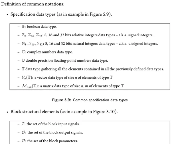
5.9 Common specification data types . . . 54
5.10 Common specification for block structural elements . . . 54
5.11 Common specification operations of block structural elements . . . 55
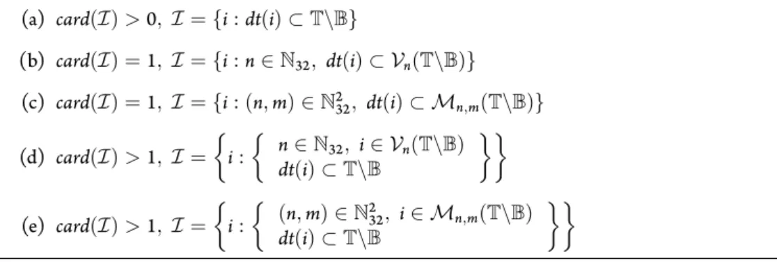
5.12 Sum allowed inputs specification . . . 55
5.14 Sum semantics specification . . . 56
5.15 Specification of the block structural elements value using UML + OCL . . . 57
5.21 Generic block specification using UML + OCL . . . 61
5.24 SMarty variability UML profile . . . 62
5.26 MinMax block specification using UML + variability profile + OCL . . . 63
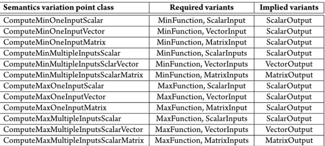
5.33 Semantics variants definition for the MinMax block . . . 68
5.38 Delay block specification using the UML . . . 71
5.41 A feature model for the MinMax block structure and semantics . . . 74
5.42 A feature model for the Delay block structure and semantics . . . 76
5.44 Delay block specification using UML + OCL . . . 81
6.1 The BlockLibrary metamodel . . . 85
6.2 The Delay block specification hierarchy . . . 86
6.5 The BlockLibrary metamodel abstract metaclasses . . . 89
6.6 The BlockLibrary Annotations metaclass definition . . . 90
6.8 The BlockLibrary metamodel structural features definition elements . . . 93
6.11 The BlockLibrary metamodel variability structure . . . 95
6.16 FM extracted from the Delay block BlockType specification . . . 100
6.17 The Configuration metaclass . . . 103
7.1 MDE architecture of the transformation . . . 115
7.24 Select lemmas verification with Why3 through SMT solvers and proof assistants . . . . 129
7.26 Overview of the BlockLibrary to Why3/WhyML transformation . . . 132
7.27 Block domain extraction of StructuralFeature data types . . . 132
LIST OF FIGURES
7.29 Signature domain extraction of MODE_INVARIANT Annotation . . . 134
7.31 Signature function with contract extraction of BlockMode specification . . . 136
7.36 Completeness goal transformation application methodology . . . 139
7.37 Disjointness goal transformation application methodology . . . 139
8.1 Configuration-specific generated metamodel example . . . 148
8.2 Counter Simulink model . . . 150
8.6 GeneAuto annotations extension metamodel . . . 153
8.8 The Observer block, its content and its parameters view in the Simulink environment . . 155
8.9 The Counter model with its counter_spec synchronous observer . . . 156
8.10 The counter_spec synchronous observer content . . . 156
8.14 An abstract synchronous observer . . . 159
9.1 BlockLibrary use for ACG verification and development . . . 166
9.2 BlockLibrary use for test procedures generation and verification . . . 168
10.1 Generic language variability specification metamodel . . . 176
D.11 String theory lemmas verification with Why3 and SMT solvers . . . 209
D.13 InPortGroup theory lemmas verification with Why3 and SMT solvers . . . 213
D.22 CommonFunctions theory lemmas verification with Why3 and SMT solvers . . . 215
D.24 OclType theory lemma verification with Why3 and SMT solvers . . . 216
D.34 OCL operations theory lemmas verification with Why3 and SMT solvers . . . 221
D.37 OCL operations theory lemmas verification with Why3 and SMT solvers (II) . . . 225
List of Tables
2.1 DAL and TQL relations . . . 11
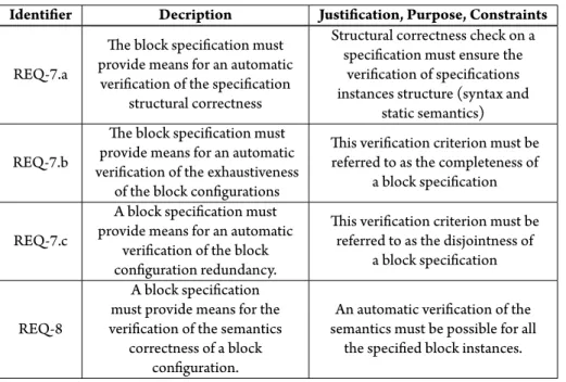
5.1 Block structure specification requirements . . . 50
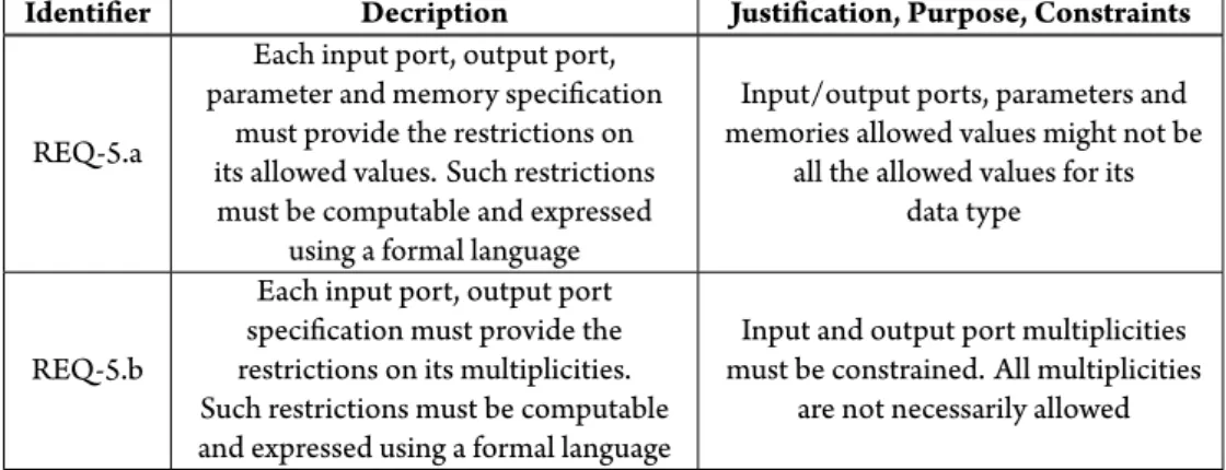
5.2 Input/Output ports structure specification requirements . . . 50
5.3 Parameters structure specification requirements . . . 50
5.4 Memories structure specification requirements . . . 51
5.5 Data type and dimensionality specification requirements . . . 51
5.6 Semantics specification requirements . . . 51
5.7 Specification verification requirements . . . 52
5.8 Related tooling requirements . . . 52
5.13 Sum allowed parameters specification . . . 55
5.34 Semantics variation point cross tree constraints . . . 68
5.43 Mapping from Delay block feature mode elements to UML classes . . . 80
6.3 Relation between Delay value, U dimension, IC dimension and M dimension . . . 86
7.3 Mapping between our type system and the Why3 types . . . 116
7.11 OCL collections characteristics . . . 123
7.13 OCL primitive numeric types operations mapping to Why theories functions . . . 124
7.14 OCL String operations mapping to Why theories functions . . . 124
7.15 OCL logical operators mapping to Why operators . . . 125
7.16 OCL arithmetic operators mapping to Why operators . . . 125
7.17 OCL relational operators mapping to Why operators . . . 126
7.18 OCL collection operations mapping to Why operators . . . 126
7.20 OCL logical property verification operations mapping to Why expressions . . . 127
7.21 OCL iteration operations mapping to Why expressions . . . 128
7.22 OCL iteration operations mapping to Why high order logic functions . . . 128
7.25 BAL expressions to WhyML translation rules . . . 131
7.34 Some blocks specification verification performances . . . 137
8.7 OCL to ACSL translation rules . . . 154
Acknowledgments
Je souhaite en premier lieu remercier Philippe Cuenot pour m’avoir initié à la recherche, aux concepts de l’ingénierie dirigée par les modèles et pour avoir suffisamment cru en moi pour me présenter à ses collègues académiques qui m’ont permis de faire cette thèse.
Cette thèse n’aurais bien entendu jamais pu être possible sans le soutient et l’aide de Marc que je remercie tout particulièrement. Je souhaite aussi le remercier pour toutes ces discussions que nous avons pu avoir durant ces quelques années passées au laboratoire, discussions qui ont tendance la plupart du temps à digresser mais qui ont toujours été très instructives.
Ces années ont été d’autant plus agréables que j’ai été accueilli dans une équipe qui m’a beaucoup apporté et avec qui j’ai passe de très bons moments. Je remercie (et je l’espère sans omission): Yamine, Philippe, Philippe, Xavier, Xavier, Aurélie, Mamoun, Manuel, Célia, Florent, Guillaume.
Je souhaiterais remercier tout spécialement celles qui ont su supporter à la fois mes boulettes et omission, les organisations de déplacement et d’évènements quasiment toujours a la dernière minute et ce toujours avec le sourire (et quelques menaces quand même): les Sylvies.
Il est bien entendu un grand nombre d’amis qui m’ont soutenu durant ces années, qui ont été la pour m’aider, me faire changer d’air et me proposer des apéros au bords de l’eau. Pour tout cela, je dis un grand merci à Stiff, Dédé, Tito, Kaka, Matt, Camille, Fabichou, Jean-Marc, Ben, Juju, Sisi, Nico, Emilie, Benoît, Annaick, Guido, Minette, Daminou, Julie, Gibon, Morue, Nico, Mawish, Toto, Erell et ceux que j’oublie.
A mes parents qui m’ont toujours soutenu et poussé à aller plus loin, et ce malgré le baobab qui peut me pousser dans la main parfois, je souhaite dédier cette thèse.
Finalement, à celle qui partage ma vie, qui a supporté mes sautes d’humeur sans soucis, celle sans qui tout cela aurais été bien plus difficile, je souhaite dire infiniment merci et je t’aime ma duchesse.
1
Introduction
Industrial size experiments and real products have shown Model Driven Engineering and Formal Meth-ods to be key assets in the development of complex safety critical systems. Both relies on domain specific modeling languages and associated verification and generation tools. Language engineering is once again an enabler to ease the development of these languages. This PhD targets highly variable languages engi-neering through a key case study in the development of safety critical systems: dataflow languages, also called block diagrams, like Simulink¹ or Scade².
We characterise the high variability of languages through the ability for languages to be composed of elements of variable structure or semantics. To handle this variability, we provide in this PhD a tooled for-mal specification methodology for our use case of block diagrams that is representative of such languages. We also develop on the uses of such formal specification for automatic code generation verification and for automatic code generators qualification in the context of embedded critical software. This work should pave the way for more generic methods for specifying high variability languages and deriving generation and verification tools from such specification.
1.1 Embedded critical software
Embedded critical software are pieces of software that take part in the global behavior of a complex system whose function is not limited to this software. For example, the control of actuators in transportation sys-tems. The purpose of the system is to provide transportation to human, whereas the embedded software system goal is often to control or command hardware pieces like sensors and actuators that provide trans-portation. Embedded software systems are used in a wide variety of environment: from everyday devices like coffee machines to the most complex systems like space probes, planes or magnetic resonance imaging scanner.
According to the functionality of the controlled/commanded system, its quality must be adapted: if for some reasons, a coffee machine software enters a wrong state that causes a coffee cup to be over-filled, the consequences are not as catastrophic as if a plane door control system enters a state causing the doors to open during a flight. The level of quality of the software in this case is related to the need for safety and reliability regarding the appearance of system failures that may have a potential impact on human lives or economic losses.
Embedded safety-critical software systems are software systems that must not experience unhandled failures leading it to a state where its safe behavior is not ensured. To our knowledge, the need for these
¹http://www.mathworks.com/products/simulink/
1.2. SOFTWARE VERIFICATION AND VALIDATION
systems reliability is the highest.
Our technology-driven society is in need for an ever increasing improvement, automation and efficiency of systems and as a consequence of their embedded and control/command software. This leads the sys-tems complexity to rise, leading to higher reliability concerns. Safety-critical software syssys-tems are also subject to such changes and are thus also affected by these issues. Their nature makes such evolution dif-ficult to manage and the assurance of safety and reliability a difdif-ficult problem to assess.
1.2 Software verification and validation
Safety-critical systems industries have long been aware of the previous problems. Ensuring a certain level of quality in their developed software is mostly done by relying on highly documented development process with a very important emphasis put on verification and validation (V&V) activities and on the emphasis of traceability information. These terms: verification and validation are differently interpreted according to the application domain. In this document, verification activities aims at ensuring that the developed software/system is rightly done according to a certain set of rules and criteria (the software is rightly im-plemented) whereas validation activities aims at ensuring that the developed software/system is the one that was expected (the right software is implemented). Traceability information provides the links be-tween the developed artifacts in the different steps of the development process. Traceability informations are among the most used artifact for highlighting the modifications operated on the software or by the software. It is thus of primary interest to ensure that traceability is ensured all along the development pro-cess of safety-critical systems and that traceability informations are provided by tools used during such development processes.
Ensuring the correctness of the whole development process and V&V activities is achieved according to regulations by fulfilling qualification or certification objectives. Qualification/Certification objectives are supposed to enforce a certain level of quality and confidence on the developed system by requiring the development process actors to provide data on the performed verification and validation activities. Qualification/Certification is domain and even product specific and the set of objectives to achieve is defined in domains specific documents among which are: ECSS-Q80A for space, DO-178 for avionics, CEI62[278|279|425] for railway, ISO26262 for automotive, CEI60880 for nuclear energy management or CEI60601-1-4 for medical applications. Other documents aims at applying on a wider variety of domain like ISO61508 dealing with Functional safety of electrical/electronic/programmable electronic safety-related systems.
In our work, we are targeting aeronautic applications as it is known as being among the more strin-gent ones with regard to safety regulation. In this domain, establishment of qualification/certification is required by authorities like the Federal Aviation Administration (FAA³) in the USA or the European Aviation Safety Agency (EASA⁴) that have been granted the authority to allow or not any civil aircraft to operate on their respective geographic area.
1.3 Model Driven Engineering and Formal Methods
From the earliest application of mathematics to model the physical world to the modern days of computer science, Model Driven Engineering (MDE) has grown as an answer to systems design and development complexity. It allows through the use of models to abstract ourselves from the system complexity and through the use of model-based tools to manipulate models. From such tools, the MDE user will gain the ability to perform model analysis, extract informations, transform models to other models, source code or documentation. The wide adoption of MDE by researchers and industrials has been driven to a large extend by technology standardisation consortium like the Object Management Group (OMG) ⁵ whom led the way to the definition of standards, or the Eclipse community that has developed and provided as
³http://www.faa.gov/
⁴https://www.easa.europa.eu/
1.4. AUTOMATIC CODE GENERATION
open source software many tools implementing these standards.
Formal Methods in computer science have been developed in order provide means to formally rea-son about the soundness of programs and electronic hardware. Formal rearea-soning settles on mathematical logic and has evolved to complex mathematical-based reasoning frameworks. A large nebula of logical field specific formal methods has since flourished allowing to analyse systems and software against various requirement domains like for example real-time, concurrency, or run-time.
While the formal nature of these methods was a restrain to its adoption in the computer science com-munity, the advent of MDE provided the necessary abstraction and automation mechanism in order to help on their adoption and use. While still not being straightforward to apply on industrial applications, formal methods advantages are no more discussed and their adoption is well on the way as advocated by their integration in industrial standards like the aeronautic one.
1.4 Automatic code generation
As system complexity is ever rising, the writing of their software is an activity that suffers from the same complexity issue. The use of tools such as automatic code generators has been experienced and adopted in order to tackle this complexity issue. Indeed tools are more likely to avoid errors than humans if they are used for repetitive activities. This is particularly true for code production activities when the requirements are precise enough like models.
Automatic code generators (ACG) are tools whose function is to apply transformation (code produc-tion) rules on input language elements and producing formatted text (such as source code). It is therefore of particular interest to formally know what are the input language elements in order to specify and de-velop the ACG itself. Scade and Simulink are widely used in the modeling of safety critical systems in the transportation domains. ACG like KCG, RTW-EC or Target Link are then used to produce the software.
1.5 The Simulink use case
Embedded control and command software are designed by engineers whose background is mostly focused on automation analysis and mathematical modeling of systems. The leading formalism in this domain is the Simulink language which is built on the mathematical scientific computing platform Matlab⁶.
Simulink models are made up of blocks linked through their ports by signals. While signals are only carrying data between blocks, the blocks are using the values obtained on their inputs and their internal state to compute their outputs. Blocks are gathered in block libraries containing their structural and se-mantics informations. Each block is configurable according to a set of parameters that allow selecting a specific structure and semantics. The context in which the block is used, defined by the data types and dimensions (if it is a scalar, a vector, a matrix) of its input ports will also impact the block semantics.
System design models written in Simulink are used as specifications for the development of software that is embedded in the end system. This development is done either by manual software writing leading to human related unavoidable errors requiring huge testing and review operations, or by automatic code generation which is more likely to cause less coding errors but whose soundness must be ensured as the tools can introduce errors.
In this PhD, we will focus on this second option and provide means to ensure such a soundness based on the formal specification of the Simulink language. Both configuration and context of use of the block implies a high level of variability of the block that must also be specified in order to fulfill this objective. 1.6 Research objectives
We have identified the following three research objectives whose fulfillment will be of principal interest in this PhD work:
1.7. CONTRIBUTIONS
• Research objective 1: Formal specification and verification of highly variable languages Highly variable languages, like block diagrams, while being widely used in the industry for the design of highly critical control and command software are most of the time under-specified and thus cannot be used as is during a full software development process based on MDE and formal methods. In order to limit the number of translation steps in the system development and thus their impact on the quality and verification of the system; it is required to formally specify the languages including their variability and to factorise existing common points between tools. Such formalisation must reduce the misinterpretations of the language and enhance the system development activities quality and as such is now required in avionics certification and qualification standards.
• Research objective 2: Uses of highly variable language formal specification for automated
gen-erated code verification
Automatic code generation is used as a replacement for traditionally humanly carried out software writing activities. From a formally defined language, the verification of an automated code genera-tion must be simplified as we may rely on the specificagenera-tion for a formalisagenera-tion of the code generagenera-tion requirements and may be able to formally reason on them. Two level of requirements are at stake here, low level requirements (LLR) that are close to the language specification and translation, and high level requirements (HLR) that may be provided as design language constructs and then trans-lated as annotations on the code for verification.
• Research objective 3: Uses of highly variable language formal specification for ACG
qualifica-tion
Automatic code generator are sensitive tools whose output and correct operation must be verified. In the context of their use for safety-critical embedded systems development, their development and verification must be done according to the system domain certification/qualification standards. Such standards require the production of detailed data regarding the conducted development and verifica-tion activities. From the formal specificaverifica-tion of the ACG input language and the formal verificaverifica-tion of the generated code, such data production must be simplified, automatised and its reliability might be improved.
1.7 Contributions
In this PhD, our purpose is to provide a first approach to the formal specification and verification of high variability languages by providing a methodology and associated tools focused on the Simulink language specification. From such a specification, we will show how to assist the verification of code automatically generated from such languages and the certification and qualification activities related to the development of safety-critical embedded software. The overall architecture of our approach is provided in Figure 1.1. Our contributions are highlighted in this Figure and detailed in the following:
1. Highly variable languages specification In the block specification approach, we detail various methodologies and technologies for the specification of highly variable language. We then discuss their advantages and drawbacks and finally provide a customised approach that better achieves this objective thanks to a formal, tooled and domain dedicated specification language. This contri-bution is developed though the case of the Simulink dataflow language and the specification of its functional blocks.
2. Specification verification transformation From a structured highly variable language specification we provide a verification mechanism translating the specification to formal languages on which man-ual or automatic formal verification can be done. We also emphasis on the verification criteria used in order to ensure variability verification correctness. We rely on state of the art verification tech-nologies having the advantage of being formal, well maintained and under active development: the Why3 toolset.
1.8. PLAN LLR/HLR Annotations HighlyUVariable Languages Specification Verification Tool Verification Tool CodeUGeneration Tool InputUdesign model Uses Imports Generates Produces Produces Output code Imports Correction Certificate Correction Certificate Certification/ Qualification Data Uses Uses
2
1
5
Specification Verification Transformation3
Semantics Annotation Injection4
HighULevel Property Injection Certification/ Qualification Data GenerationFigure 1.1: Code generation verification strategy
3. Semantics annotation injection We advocate our ability to automatically inject input languages re-lated semantics informations as annotations on automatically generated code from formally specified highly variable languages. We then highlight on the formal verification of these semantics annota-tions on the generated code and on the guarantees it provides on the verification of automatic code generators outputs.
4. High level properties injection We argue on the possibility to rely on language specifications in or-der to translate high level properties (HLR) expressed using these languages. Such properties might then be manually or automatically verified with the help of state of the art verification tools.
5. Certification/Qualification data generation Highly variable languages automated code genera-tors verification is strongly dependent on the ability to provide a specification for their input lan-guages. We argue on the wide possibilities offered by a formally verified formal specification of such languages in order to automatically generate reliable data that can be used in certification/qualifica-tion activities.
1.8 Plan
We divided this PhD into 2 parts comprising 10 chapters and 5 appendix providing additional informations on some elements detailed in this PhD:
• Chapter 1: introduces the PhD work and states the challenges we tackle. • Chapter 2: presents the industrial context in which our PhD work evolves. • Part 1: Highly variable languages formal specification
– Chapter 3: presents the state of the art in programming languages formal specification.
– Chapter 4: focuses on dataflow languages specificities and presents the challenges for their
spec-ification.
– Chapter 5: proposes dataflow languages symbols specification methodologies using
1.8. PLAN
– Chapter 6: defines our BlockLibrary specification language.
– Chapter 7: describes our BlockLibrary specifications language formal verification
method-ology and tooling.
• Part 2: Automatic code generation verification based on the block library specification
– Chapter 8: gathers the block library specification use for automatic code generation verification. – Chapter 9: proposes block library specification uses for certification/qualification activities. – Chapter 10: concludes the principal part of the PhD and outlines future research directions.
• Appendix
– Appendix A: contains complete examples of block specification.
– Appendix B: depicts the grammar for our implementation of the OCL language. – Appendix C: provides the grammar for our custom action language.
– Appendix D: contains the Why3 theories developed during this PhD.
Part I
Critical embedded systems design and
implementation
2
Industrial context
Establishing the certification of a developed system or the qualification of a tool for the development or verification of systems is checked by certification authorities. Their mission is to ensure the achievement of the required objectives according to the assurance level that needs to be reached. Development techniques and technologies used for system development are assessed by certification authorities in the domain of interest. These ones will only allow the use of reliable technologies and techniques for safety-critical em-bedded software systems development.
In this chapter we will go in details on the current status of industrial uses, limitations and constraints applied on embedded critical software systems development. We will first detail recent updates of qualifi-cation/certification methodologies in this context and their impact on system development. We will then emphasize on the use of domain specific languages (DSL) and their interest in this field. Finally, the use of Automatic Code Generators (ACG) for the development of embedded critical software will be detailed through two industrial-size ACG tools.
2.1 Certification/Qualification
The development quality of the safety-critical embedded software has been, for many years now, ensured by applying precise and constraining development processes on each activity of the system development: from requirements elicitation to concrete embedding of code through software design, code production and code verification. For each of these activities data are produced aiming at providing evidence of the means used for the activity achievement. These data are mandatory to provide parts of the informations required by certification standards.
In this work, we will focus on the application of DO-178 certification document as it is used for the regulation of aeronautical software systems development activities that are, to our knowledge, the more stringent ones.
2.1.1 Terminology
In the following, we will use both qualification and certification words.
Certification stands for the process of ensuring that a product (system or equipment) is “approved” for
use. It is not the software by itself that is certified. Certified system software components development must be defined in the Plan for Software Aspects of Certification (PSAC) containing the required infor-mations about the developed software in order to determine “whether an applicant is proposing software life cycle that is commensurate with the rigor required for the level of software begin developed” [114].
2.1. CERTIFICATION/QUALIFICATION
Qualification is used in the context of tools when these ones are expected to be used for the “elimination,
reduction or automation” of certification activities “without its [the tool] output being verified” [114]. 2.1.2 DO-178B– Software Considerations in Airborne Systems and Equipment Certification
DO-178B is the reference certification document for most current airborne systems and equipment cer-tification. It provides a set of objectives to be fulfilled in order to ensure the system development safety operations. DO-178B defines 5 level of systems to be certified, these levels reveal the criticality of the sys-tem with regards to on-board safety. These levels are referred to as Design Assurance Levels (DAL) and are classified from A to E, A being the most critical one that applies to safety-critical systems like fly-by-wire, landing gears or doors opening systems; and E being the less critical one that applies to non safety related systems like entertainment systems for example. Fulfillment of each objective is dependent of the DAL that must be reached by the certification applicant. DAL levels have first been introduced and stan-dardized in the Aerospace Recommended Practice Guidelines For Development Of Civil Aircraft and Systems (ARP4754).
In addition to the DAL, DO-178B defines the degree of independence between activities of the devel-opment (if needed) that must be applied in order for the objective to be achieved. Objective fulfilment with independence means that requirements, development and verification activities must be produced by different mean and persons. The independence may also be related to the developer conducting the mean itself.
2.1.3 DO-178C– Software Considerations in Airborne Systems and Equipment Certification
The work done for the release of DO-178C is a strong revision effort of the previous DO-178B version to take into account the clarifications provided throughout the years in the Frequently Asked Questions (FAQ ) and the Certification Authority Software Team (CAST) papers released after the DO-178B and to handle new technologies like object oriented programming, model driven engineering and formal meth-ods.
DO-330– Tool qualification according do DO-178C
A major shift between DO-178B and DO-178C is on the use of tools for safety-critical systems develop-ment. Throughout the years, efforts have been done on the development of domain-specific and objective-centered tools used as an assistance in safety-critical systems developments. They are developed with the goal of obtaining certification credits for their use. This leads to the natural question of the qualification of these tools as they are likely to impact the final software quality.
DO-178C defines three tool qualification criterion used to categorize the tools according to their pur-pose and potential impact. These ones are:
• Criteria 1: A tool whose output is part of the airborne software and thus could insert an error. • Criteria 2: A tool that automates verification process(es) and thus could fail to detect an error, and
whose output is used to justify the elimination or reduction of: 1. Verification process(es) other than that automated by the tool, or
2. Development process(es) that could have an impact on the airborne software. • Criteria 3: A tool that, within the scope of its intended use, could fail to detect an error.
Criteria 1 tools are tools that are producing part of the embedded software. Criteria 2 tools aims at au-tomating the verification of embedded software whose result is used in order to leverage other verification processes. An example of criteria 2 tool, would be a tool allowing to automate some verifications on the source code of the developed embedded system and based on this verification and the confidence that is put on the tool to avoid to insert runtime verification mechanisms. Criteria 3 tools are simple verification
2.1. CERTIFICATION/QUALIFICATION
tools used only for verification purpose whose results are not used for the leveraging of other certification activities.
The previous release from 1992, DO-178B, defined two kind of tools: development tool (criteria 1) and verification tools (criteria 3). In DO-178C we see that a third kind of tool has been added: Criteria 2 tools. These tools are of specific interest as their results might be used to leverage other verification or development activities for which certification should be provided. This impact on other activities leads them to the necessity to provide greater confidence for criteria 2 tools than for criteria 3.
According to the chosen criteria, tools qualification activities will differ. These activities are classified using Tool Qualification Level (TQL) defined in DO-178C and matches to a pair of tool criteria and soft-ware Design Assurance Level (DAL). According to the chosen TQL, a specific set of objectives have to be fulfilled to ensure the tool qualification. “For a tool that can introduce an error in the outputs of a tool, the applicable TQL is the same as the tool being developed. For a tool that cannot introduce an error in the output of the tool, but may fail to detect an error in the tool life cycle data, the applicable TQL is TQL-5” [114]. The lower the TQL is, the stronger is the set of objectives to match. TQL ranges from TQL-1 to TQL-5. The relations between TQL and embedded software DAL is provided in Table 2.1.
DAL Criteria 1 2 3 A TQL 1 TQL 4 TQL 5 B TQL 2 TQL 4 TQL 5 C TQL 3 TQL 5 TQL 5 D TQL 4 TQL 5 TQL 5
Table 2.1: DAL and TQL relations
From the definition of the criterion and the TQL, one can refer to a specific document focused on the certification of tools. This ’companion’ document to DO-178C is the DO-330 [115] (Software Tool Qual-ification Considerations Companion). This document is, in fact, a rewriting of DO-178 focusing on tools used for the development of safety critical systems.
Technology specific approaches in DO-178C
Since DO-178B release, software design, development and verification techniques have evolved leading to the emergence and adoption of new technologies and approaches by industrial users. With this adoption came the necessity to ensure the safety of the use of these techniques in safety-critical software develop-ment. Considerations regarding the use of these specific technologies during the software development have been detailed in external ’supplement’ documents: DO-331 [6] on model-based development and verification; DO-332 [7] on object-oriented technologies and related techniques; and DO-333 [8] on for-mal methods. The choice to rely on external documents to deal with the use of these approaches instead of integrating it directly to DO-178C was more reasonable as it eases the transition between DO-178B and DO-178C whilst allowing the use of alternative techniques for the certification of systems.
Technology-specific ’supplement’ documents provides the modification to objectives, activities, explana-tory text, and software life cycle data that can be applied to DO-178C when technology-specific develop-ment and verification is used. Those docudevelop-ments explain in which context and for which activities linked to certification, technology-specific approaches can be used instead of classical approaches.
2.1.4 DO-330– Software Tool Qualification Considerations Companion
In the DO-330 document, guidelines regarding the certification data that must be produced for tools qual-ification are provided. Data are to be produced according to the level of criticality of the activity the tool is meant to replace. Indeed, tools ensuring coding standard respect or aiming at limiting the use of tests does not have the same potential impact on the final produced software.
2.1. CERTIFICATION/QUALIFICATION
The DO-330 document is meant to be domain-independent and thus must be applicable on tools used in any domain where qualification is needed and then not necessarily on DO-178 related systems. Indeed, other domains like space or automotive seems to agree that DO-330 is also sensible in their context. Tools are used in their operational environment and thus are qualified according to this environment. Thus, as soon as a qualified tool environments changes, qualification must be re-considered.
Tool qualification relies on, among other data, providing the Tool Requirements (TR) and the Tool Operation Requirements (TOR).
• TR “describe all the tool functionality”, this encompasses among others: the description of the tool functions and features (modes of operation); documentation (user instructions, installation instruc-tions, error messages, ...); and informations about failure modes, abnormal operainstruc-tions, inconsistent inputs response.
• TOR “define the tool’s functionality and interface from a software life cycle process perspective” [115]. One of the main aspects for a criteria 2 or criteria 3 tool qualification is to provide evidences on the respect of the TOR by the tool implementation.
A tool must be validated according to the tool operational verification and validation process. Both have the purpose of ensuring that the tool complies with its user requirements.
Here we roughly provided an overview of the tool qualification according to DO-330. Tool qualifica-tion requires many addiqualifica-tional steps that are not menqualifica-tioned here as it is not our purpose to fully detail the qualification process. Further details on the use and benefits of the DO-330 document can be found in Frederic Pothon’s DO-330 focused document [126].
2.1.5 DO-331– Model-Based Development and Verification Supplement
The use of models has become a typical approach for the specification and development of complex sys-tems. These ones provide the benefits of abstraction and formalisation. A model is defined in DO-331 document as “an abstract representation of a set of software aspects of a system that is used to support the soft-ware development process or the softsoft-ware verification process”.
This ’supplement’ document provides informations on the use of models in the development process of safety-critical systems. According to DO-331 document, a model must have the following characteristics:
a The model is completely described using an explicitly identified modeling notation.
b The modeling notation has a precise grammar (also called “syntax”) and meaning (also called “se-mantics”). The modeling notation may be graphical and/or textual.
c The model contains software requirements and/or software architecture definition.
d The model is of a form and type that are used to direct analysis or behavioral evaluation as supported by the software development process or the software verification process.
If a model complies with the previous characteristics, one may benefit from its use for: “Providing un-ambiguous expression of requirements and architecture; Supporting the use of automated code generation; Sup-porting the use of automated test generation; SupSup-porting the use of analysis tools for verification of requirements and architecture; Supporting the use of simulation for partial verification of requirements, architecture, and/or Executable Object Code.”[6]
Models can be well defined and formalised, this makes them interesting artifacts for the specification, development and verification of safety-critical embedded systems. DO-331 can also be used for the devel-opment of tools used in the develdevel-opment of such systems and thus benefit to the qualification activities.
For example, a model containing system requirements can be refined until it is expressed as executable code or as test cases to be checked on the system code; model can be fed to ACG tools in order to automat-ically generate code or configuration files; it can also be used as a configuration file of the automatic code
2.1. CERTIFICATION/QUALIFICATION
generator itself; if a model can be simulated, its simulation results can be used as oracles for the verification of test cases execution on the final object code; metamodels can be used to model languages in the TOR and TR documents. This last example, is one of the purpose of the experiments conducted in this PhD. 2.1.6 DO-332– Object-Oriented Technology and Related Techniques Supplement
Object-oriented technologies are nowadays widely used in software development. This use for the devel-opment of safety-critical systems has increased in the last years. As for any other programming paradigm used in this context, safety and integrity of development techniques need to be ensured.
DO-332 document “provides guidance for the production of software using object-oriented technologies and related techniques for system and equipment that performs its intended function with a level of confidence in safety that complies with airworthiness requirements”.
Object-oriented techniques and technologies introduces a set of features and potential issues that does not exists in traditional embedded systems development approaches. DO-332 defines object-oriented: basic concepts – classes and object, types and type safety, Liskov substitution principle, hierarchical en-capsulation, polymorphism, function passing and closures and method dispatch – ; and key concepts – in-heritance (and related subtyping), parametric polymorphism, overloading (ad hoc polymorphism), type conversion, exception specification and handling, dynamic memory management, object pooling, acti-vation frame, manual and automatic heap management and virtualization techniques. This supplement provides supporting informations and advices on the use of the previously cited concepts such as: ensure type conversion uses are safe (for example downcasting my cause problems), ensure that overloading is not confusing. Regarding traceability the supplement provides traceability objectives that are adapted to object-oriented architecture such as if subtyping is used, traceability has to be done to the sub-classes in order to, for example, strengthen the traceability by ensuring that traced element are not overloaded. 2.1.7 DO-333– Formal Methods Supplement
DO-333 deals with the use of a specific family of formal methods in the context of safety-critical software systems: software-related formal methods. These methods are defined in this document as “mathematically based techniques for the specification, development, and verification of software aspects of digital systems”
The definition of this formal methods ’supplement’ document has been supported by industrial actors in the field of safety-critical systems like the Airbus Group or Rockwell Collins. These actors have worked during the last decades with these approaches brought by computer science research. Improvements in the usability of formal verification techniques and methods has motivated their use and is providing “the ex-pectation that, as in other engineering disciplines, performing appropriate mathematical analyses can contribute to establishing the correctness and robustness of a design”.
DO-333 document identifies applicability of formal methods in order to replace traditional (DO-178C) certification activities or objectives. Related activities are identified as “modeling and analysis”. According to DO-333 document, it is the combination of formal modeling and formal analysis that is producing a formal method. A formal model is defined as a model that “should have an unambiguous, mathematically defined syntax and semantics”, a formal analysis is defines as such “if its determination of a property is sound. Sound analysis means that the method never asserts a property to be true when it is not true.”
Several concrete applications of formal methods in the certification of safety-critical software systems have been conducted. The Airbus Group applications as presented by Souyris in 2009 [140], Bedin França in 2011 [70] or Moy in 2013 [111] or the Rockwell Collins ones by Cofer in 2014 [43] relates some of the success stories in this field. An extensive discussion on advances regarding software certification is provided in a 2013 Dagstuhl report [44].
DO-333 can also be used for the development of tools used in development of safety critical systems. Assisted or automated proof can be used to assess consistency and completeness of requirements in TOR and TR, to ensure correctness of tools with regards to TOR and TR. This is one of the purpose of the experiments conducted in the PhD.
2.2. THE NEED FOR DOMAIN SPECIFIC LANGUAGES
2.2 The need for domain specific languages
Software development relies on programming languages. Embedded software systems are nowadays mostly developed using general purpose programming languages like C or Ada. These are selected for their ex-pressiveness and efficiency (regarding both memory and computing power use). These properties are also considered as a problem when developing applications for which a high level of confidence is required as their expressiveness (the variety and number of available code constructs) and efficiency (obtained by hiding complex memory management operations) makes the verification of their correct operation more complex.
While embedded software systems became more complex, the necessity for their specification and ac-curate development arose. Tackling this problem is often done by relying on DSL whose primary purpose is to provide an higher level more focused view of the developed systems and automated code generators that bridge the gap with programming languages. High level development of software systems allows to focus on the functional part of the software development while abstracting from programming languages complexity. These more abstract description are usually called models even if they can be quite similar to programs. DSL are then named DSML. We will rely on this wording there after. We detail the DSML technological viewpoint through the description of Model Driven Engineering (MDE) in Section 3.2. 2.2.1 From DSML to embeddable software through automatic code generation
While a DSML may provide an abstract view of the software system, they cannot be usually directly used as embedded software. It is thus required to translate them to common programming languages used in embedded software. This phase is related to the compilation used for translating classical low level pro-gramming language to executable machine code. Compilation of high level conception language to em-beddable programming languages is done using automatic code generation tools.
ACG advantages and drawbacks
Since a few decades, ACG tools are widely used in industrial applications. Their interest for software de-velopment is multiple:
• Code production efficiency: Using ACG makes it possible to produce code from a model by relying on the use of the tool. A modification of the input model can automatically be impacted on the generated code. During the development process, code is tested at various level and bugs or flaws are detected. If they are reported as being present at the design level, these errors can be corrected and then the ACG allows to update them instantly. The efficiency of adding new features is also improved as the time needed for their development is lowered.
• Code quality improvement: An ACG is producing code according to code production rules. These rules are developed in order to respect standard coding rules making the generated code cleaner and respectful regarding standards. The automated production of code also normalises the generated code structure and content and thus make it easier to verify.
• Code traceability: Code generation rules allows to match sections of generated code with DSML elements. Each generated element must thus be traceable to a DSML construct. As a model is func-tionality related, its elements are more easily linked to the software requirements. Through the trace-ability mechanism, generated code constructs tracetrace-ability to requirements is by consequence eased. This is a huge advantage as such a traceability is required by certification/qualification standards. While ACG are helpful tools for the development of embedded systems, they are still developed by human beings and thus their reliability must be demonstrated. In it indeed impossible to rely on the code produced by using an ACG if the ACG itself is not reliable. ACG are complex pieces of software and thus they need to be reliable, usable and useful. If not, the generated code must be verified.
2.3. OUR LOCAL RESEARCH CONTRIBUTIONS TO THE ACG DEVELOPMENT FIELD
ACG verification
Compilers verification can be done using multiple approaches [55]. The same ones can be used for the verification of ACG as their purpose, use and structure are very close:
• Traditional approach: Compiler verification is done in most cases by testing and proofreading. While having the obvious disadvantage of not being exhaustive, these techniques are widely used and are considered as being acceptable to some extend in industrial applications. Such traditional verification is done by first proofreading each translation rule and then by verifying each one with multiple test cases with a high coverage like MCDC. From these activities, one can get a light assurance of the ACG correct operation.
• Proved development: At the opposite side of the testing/review use for the verification of an ACG is the proved development approach providing the proof of correction of the ACG. By relying on proven development the verification is done once and for all as there is no need for verification while using the tool. One of the earliest example of proved development was provided by Milner et al. [109]. The current state of the art is the work done by Leroy et al. [26,100,101] around the Com-pCert project. These works provides a strong foundation on the feasibility of the approach and its potential applications [70,140]. Despite the ground-breaking nature of the CompCert work, the approach remains of difficult access for an industrial diffusion because of its technological and the-oretical complexity. The AbsInt SME, well known for developing the aiT Worth Case Execution Time (WCET) analyser and industrializing the Astrée static analyser targets to industrialise soon CompCert.
• Translation validation: During the SACRES and SafeAir I and II research projects, Pnueli proposed not to rely on the verification of the compiler itself but on the systematic verification of the generated elements. This approach referred to as Translation Validation (TV) [124], has the advantage of not verifying the various steps composing the ACG that is complex but has the drawback of necessitating the verification at each use of the ACG. TV have shown its applicability [95,159] but suffers from the fact that it is very complex to automatically verify the ACG without the knowledge of the trans-lation (compitrans-lation, code generation) semantics. It is easier to achieve with the knowledge of the translation semantics and of a mean to analyse the generated code to prove its semantics matching to the translated input semantics. CompCert relies on TV for the hardest parts like graph coloring for register allocations[129].
2.3 Our local research contributions to the ACG development field
In the past decades, new approaches regarding the definition and verification of ACG have been inves-tigated in the ACADIE team where I conducted my PhD. These investigations have been done in coop-erative projects like TOPCASED, ES_PASS, GeneAuto, OPEES, QuarteFT, Hi-MoCo and Projet-P, openETCS, CESAR or Spacify. Most of these are related to the integration of MDE and/or formal methods in the development and/or verification of the ACG in collaboration with industrial partners and qualification experts. We will detail here some research projects the ACADIE team has been participating on.
2.3.1 The GeneAuto ACG example
GeneAuto¹ is an open code generator project for transforming a set of high-level graphical modelling languages to selected common textual programming languages (see [28,76,148,149] that describe the evolution of the toolset in the last 6 years). It currently supports subsets of Simulink, Stateflow and Scicos as input and C and Ada language as output. It is intended to be used and certified for critical