OATAO is an open access repository that collects the work of Toulouse
researchers and makes it freely available over the web where possible
Any correspondence concerning this service should be sent
to the repository administrator:
[email protected]
This is an author’s version published in:
http://oatao.univ-toulouse.fr/21066
To cite this version:
Gu, Jinglian and You, Xinqiang and Tao, Changyuan and Li, Jun and
Gerbaud, Vincent
Energy-Saving Reduced-Pressure Extractive
Distillation with Heat Integration for Separating the Biazeotropic Ternary
Mixture Tetrahydrofuran–Methanol–Water. (2018) Industrial &
Engineering Chemistry Research, 57 (40). 13498-13510. ISSN 0888-5885
Official URL:
https://doi.org/10.1021/acs.iecr.8b03123
Energy-Saving Reduced-Pressure Extractive Distillation with Heat
Integration for Separating the Biazeotropic Ternary Mixture
Tetrahydrofuran−Methanol−Water
Jinglian Gu,
†Xinqiang You,
*
,‡Changyuan Tao,
†Jun Li,
*
,†and Vincent Gerbaud
§†
School of Chemistry and Chemical Engineering, Chongqing University, Chongqing 401331, China
‡
Fujian Universities Engineering Research Center of Reactive Distillation Technology, College of Chemical Engineering, Fuzhou University, Fuzhou 350116, Fujian China
§
Université de Toulouse, INP, UPS, LGC (Laboratoire de Génie Chimique), 4 allée Emile Monso, F-31432 Cedex 04, Toulouse, France
ABSTRACT: There is rich literature on the separation of binary azeotropic mixtures, whereas few studies exist on the separation of biazeotropic ternary mixtures. In this work, we propose a systematic approach for energy-efficient extractive distillation processes for the separation of a biazeotropic mixture that involves thermodynamic insights via residue curve maps and the univolatility line to find the optimal entrainer and operating pressure, global optimization based on a proposed two-step optimization procedure, and double-effect heat integration to achieve further saving of energy consumption. An energy-saving reduced-pressure extractive distillation (RPED) with a heat integration flowsheet is then proposed to achieve the minimum total annual cost (TAC). The results show that the TAC, energy
consumption, and exergy loss of the proposed RPED with heat integration are reduced by 75.2%, 80.5%, and 85.8% compared with literature designs.
1. INTRODUCTION
Tetrahydrofuran (THF) and methanol are important organic solvents in chemical, pharmaceutical, and biochemical engineering, etc. The related processes produce large amounts of THF−methanol−water mixture, and economically separat-ing this mixture is an urgent mission in reducseparat-ing energy cost and CO2emissions.1−3 However, it is impossible to separate THF−methanol−water mixture by simple distillation, due to the presence of two binary azeotropes. At atmosphere, THF− methanol forms a minimum azeotrope at 332.94 K with 50.79 mol % THF, and THF−water gives another minimum azeotrope at 336.58 K with 82.87 mol % THF. Therefore, a special technique like extractive distillation (ED) is needed.
ED is realized by feeding an additional entrainer, which could keep the relative volatility of the azeotrope components far away from unity. For the separation of binary azeotropes, Modla4 investigated conventional ED, thermally integrated ED, and extractive dividing-wall columns for separating the minimum azeotropic mixture of methanol−toluene with the intermediate entrainer trimethylamine and found that the extractive dividing-wall column could reduce the energy cost by 45%. However, Luyben5 improved Modla’s conventional ED process by largely reducing the entrainer flow rate and concluded that the improved process gives a 50% reduction in
energy consumption compared to the conventional ED process. The result reminds us that it is necessary to find the optimal conventional ED design before further considering energy-saving configurations.
For the separation of ternary azeotropes, Timoshenko et al.6 proposed a set of comprehensive alternative ED configurations including both a conventional three-column flowsheet and a partially thermally coupled flowsheet for ternary mixtures of different phase equilibriums. Luyben7 investigated the ED process for the ternary mixture of benzene−cyclohexane− toluene and explored the dynamic controllability of the process. Zhao et al.8 compared the heterogeneous azeotropic distillation and ED processes for the mixture of ethanol− toluene−water and declared that ED is much more attractive in terms of total annual cost (TAC). Further, mixed entrainers are employed to reduce the energy cost for the separation of THF−ethanol−water azeotropic mixture.9
Since distillation is still energy-intensive,10from the view of thermodynamic insight for extractive distillation, we propose
for the first time, as far as we know, a new three-step strategy to reduce the energy consumption and improve the perform-ance of the ED process. (1) Find a better entrainer. This includes a heuristic method (based on the literature, molecular classification,11 selectivity and capacity,12,13 thermodynamic insight,14 and computer-aided molecular design15,16). The
issues of why one extractive column could break two biazeotropes and how to select a better entrainer without tedious optimization are solved. (2) Improve the design. This refers to changing operating pressure17−19and using different
optimization methods, such as a sequential iterative optimization procedure,9,20 a two-step optimization
proce-dure,21,22mixed integer nonlinear programming,13,23a genetic algorithm,24−27and an artificial neural network.28How to find
the possible direction for reducing energy consumption is illustrated by a ternary map and univolatility line. (3) Integrate the heat. This covers product to feed stream heat integration (HI),29,30double-effect HI,31,32thermal coupling scheme and
dividing-wall column,33−38 heat pump,39,40 and so on. It
involves how to choose the configurations of heat integration, which one is better, and if there is a potential advantage when changing operating pressure.
For a ternary mixture of THF−methanol−water, Raeva and Sazonova2tried to use ethylene glycol (EG) as entrainer with
the aim of validating their entrainer selection rule, but no further optimization and heat integration techniques were considered. In this study, the above three aspects are systematically investigated: first, DMSO is used for the first time, as far as we know, as a better entrainer for the THF− methanol−water system, and the conventional three-column extractive distillation process at atmospheric pressure is optimized by the two-step optimization procedure with total energy consumption per product unit (FEC) as an objective function and TAC as the decision-determining criterion. The reason for selecting the specific flowsheet is given. Second, the conventional ED (CED) design is improved by considering thermodynamic insight. The reason why reduced pressure ED (RPED) could save energy consumption for the studied system is illustrated and the optimal pressure is obtained. Third, double-effect HI (DEHI) is applied to the RPED process to further improve the energy efficiency and reduce TAC and CO2 emissions. A comparison between DEHI−RPED and −CED is done to explain the potential advantages of RPED over CED when considering the DEHI process.
2. METHODS
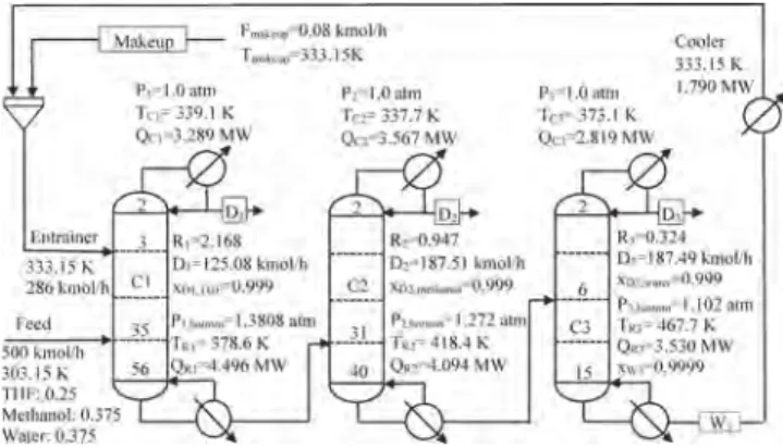
2.1. Extractive Distillation Process Flowsheet. The extractive distillation process flowsheet for the separation of THF−methanol−water with DMSO as entrainer is displayed inFigure 1. There are three columns: extractive column (C1), distillation column (C2), and entrainer regeneration column (C3). The entrainer and azeotropic mixture are fed at different trays of C1, and thus, a new extractive section is raised. In this extractive section, the entrainer interacts differently with the components and breaks the two binary azeotropes at the same time. THF with little impurities is recovered from the top of C1. Methanol, water, and entrainer are discharged from the bottom of C1 and then fed into C2. In column C2, methanol is obtained in the top, and water and entrainer are discharged from the bottom and then fed into C3. In column C3, water with impurities is recovered as top product and entrainer is discharged from the bottom for cyclic utilization after cooling down. For entrainer makeup stream, it is set equal to the
entrainer loss in the three products and calculated by the calculator model built in Aspen Plus.
The flow rate of the ternary azeotropic mixture is 500 kmol/ h, with a content of 25 mol % THF, 37.5 mol % methanol, and 37.5 mol % water. The purity of product THF, methanol, and water in the distillates are all set to be 99.9 mol %. The vapor− liquid equilibrium of THF−methanol−water−DMSO is described by the nonrandom two liquid (NRTL) property model with Aspen Plus built-in binary parameters (seeTable S2in the Supporting Information).
2.2. Energy Consumption, TAC, and Exergy Loss. Energy consumption is one of the main criteria for comparing different designs of the extractive distillation. In order to simultaneously take the three columns into account, we use a new objective function full energy consumption equation (FEC), which represents the energy cost per unit product (kJ/ kmol) MQ mQ MQ mQ MQ mQ mQ kD D x x x x min FEC ( )/( ) subject to 0.999 0.999 0.999 0.9999 D D D W R1 C1 R2 C2 R3 C3 cooler 1 2 THF, 1 methanol, 2 water, 3 DMSO, 3 = + + + + + + + ≥ ≥ ≥ ≥ (1) where QRiand QCiare the reboiler and condenser duties of the column Ci (i = 1, 2, 3), D1and D2are the distillate flow rate of C1 and C2, respectively. Qcooler is the heat duty of the heat exchanger for cooling down the entrainer recycling stream. Factor m reflects the price difference between the condenser and reboiler heat duties (m = 0.036: energy price index). Factor M reflects the prices of heat steams and equals 1, 1.065, or 1.280 when low-, middle- or high-pressure steams are used, respectively. Factor k means the weight coefficient of the two products THF and methanol, which equals 11.9. There are three advantages of using FEC as an objective function: (1) it represents not only the amount of the energy consumption but also the grade of the steam. (2) The energy cost of the condenser and the reboiler are united. (3) It has the ability of optimizing the three columns simultaneously rather than sequentially.
Figure 1.Simulation setup and optimal design of THF−methanol− water extractive distillation with DMSO (the design of case 2).
TAC is helpful for judging different designs from an economic view. Therefore, TAC has been commonly employed as the decision-determining criterion for different designs. It is calculated by the following equation:
TAC capital cost
payback period operating cost
= +
(2) The cost formulas used in our previous study41 are
employed for the capital cost calculation, and a three-year payback period is used (see Table S1 in the Supporting Information). For the capital cost, only the major equipment like column shell, tray, condenser, reboiler, and heat exchanger (for cooling down the recycled entrainer stream) are considered while other costs such as the pumps, pipes, and valves are neglected. For the energy cost, the heat duties in condenser and reboiler of the three columns are considered as well as the heat exchanger for cooling the recycling entrainer. The pressure drop per tray is assumed as 0.0068 atm42and the tray efficiency is 85%43 for calculating the capital cost of the columns.
Exergy loss,44,45as an important indicator for the judgment of an ED process, is employed to evaluate the thermodynamic efficiency of different designs of the ED process. The exergy loss, denoted as Exloss, is the difference between the exergy entering the system and the exergy leaving the system (seeeq 3). The lower the exergy loss of a process, the higher the thermodynamic efficiency and the less the energy required. Suphanit et al.45proposed that the exergy loss of a distillation column could be calculated on the basis of a simple overall exergy balance across the column. For the studied three-column system, the exergy input is provided by the exergy of the fresh feed flow and the entrainer makeup flow plus the exergy input from the reboilers. The exergy output of the system is given by the exergy of the three products flow and the exergy leaving the condenser.
Exloss=
∑
Exin−∑
Exout (3) Q T T Ex Ex Ex 1 i i i in feed makeup 1 3 R 0 S∑
= + +∑
− = L N MMMMM \^]]]]] (4) Q T T Ex Ex 1 m m j i j out 1 3 D 1 3 C 0 C∑
=∑
+∑
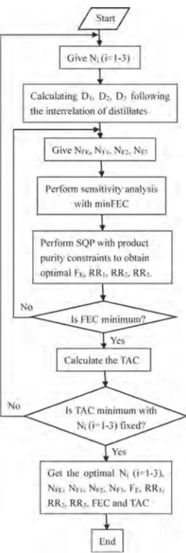
− = = L N MMMMM M \ ^ ]]]]] ] (5)2.3. Two-Step Optimization Procedure. We extended the two-step optimization procedure for two columns22,46to a three-column extractive distillation process for the studied system. The procedure is shown in Figure 2. First, the sequential quadratic programming (SQP) method built in the Aspen Plus simulator is used for the optimization of the process by minimizing FEC under product purity and recovery constraints over the continuous variables: reflux ratio (RR1, RR2, RR3) and the entrainer flow rate (FE). Second, the sensitivity analysis is performed for the discrete variables: the four feed locations (NFE, NF1, NF2, NF3) and the three distillates (D1, D2, D3), while step 1 (SQP) is run for each set of discrete variables. The optimal one is the one with lowest energy consumption, and the TAC of each separation sequence is calculated for comparison.
3. CONVENTIONAL EXTRACTIVE DISTILLATION
3.1. Why the Specific Flowsheet Is Selected. For the separation of a ternary mixture with two binary azeotropes, two extractive columns and one regeneration column are usually employed to break the two binary azeotropes in sequence; hence, two entrainers are needed and normally mixed entrainers are more economic for the process.9 However, if
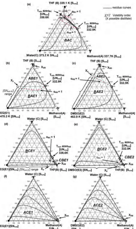
there is one entrainer that could make the two binary azeotropes disappear, one entrainer is feasible to separate the ternary mixture in two independent extractive columns. More specifically, one entrainer with one extractive column, one distillation column, and one entrainer regeneration column, as shown inFigure 1, is feasible to separate a ternary mixture with two binary azeotropes if the one special entrainer could first separate the shared component of the two binary azeotropes. To illustrate this feasibility, the ternary maps with the univolatility line, residue curve, and volatility order for methanol−THF−water with EG and DMSO in a 2D model47are shown inFigure 3.
Let us recall the general feasibility criterion for binary mixture in the extractive distillation under infinite reflux ratio.14It states that “homogeneous extractive distillation of A−B mixture with entrainer (E) feeding is feasible if there exists a residue curve connecting to A or B, following a decreasing (increasing) temperature direction inside the region where A or B is
Figure 2. Two-step optimization procedure for the extractive
the most volatile (the heaviest) component of the mixture”. Taking EG as example, as shown in Figure 3b for methanol−THF azeotrope, the univolatility line divides the ternary map into ABE (upper side) and BAE (lower side). In region ABE, although A is the most volatile component, there is no residue curve connecting A. Therefore, region ABE is unfeasible. However, in region BAE, there is a residue curve connecting B following the increasing temperature direction where B is the most volatile, so this region is feasible as it satisfies the general feasibility criterion. Meanwhile, we could confirm that B (THF) is the top distillate of the extractive column, a direct split should be employed, and there is minimum entrainer-to-feed flow rate ratio depending on xp(the intersection of the univolatility line and the triangle side). Differently, for THF−
water, as displayed inFigure 3d, the process is feasible in upper region BCE while unfeasible in lower region CBE. Fortunately, in region BCE, B (THF) is also the top distillate in a direct split flowsheet with the limiting condition of minimum entrainer usage. This is why one entrainer could break two binary azeotropes in one extractive column. The entrainer DMSO, as shown inFigure 3c,e is the same as entrainer EG. Once the shared component THF is distillated out, there is no azeotrope among the rest of the ACE system, as shown in
Figure 3f,g, and it could be separated by two simple distillation columns in a direct split.
3.2. Why DMSO is Better than EG.FromFigure 3, the ternary maps of methanol−THF with EG and DMSO belong to class 1.0−1a−m2, while that of THF−water with EG and Figure 3.Thermodynamic features and univolatility lines of methanol−THF−water with EG (a, b, d, f) and DMSO (a, c, e, g).
DMSO pertains to class 1.0−1a−m1. The distinction is that the univolatility line (αAB = 1) reaches the AE side (lower boiling temperature azeotropic component and entrainer) or BE side (higher boiling temperature azeotropic component and entrainer). Following the general feasibility criterion,14for class 1.0−1a−m2, the feasibility criterion is satisfied in the volatility order region BAE (Figure 3b,c). In region BAE, component B THF is a saddle (Srcm) in the residue curve map (RCM) and cannot be obtained by azeotropic distillation.48 Thanks to the entrainer (EG or DMSO) feeding at an upper tray rather than the main feed tray, an extractive section occurs among them in the extractive column. The stability of the singular points in the extractive composition profile is the reverse of that in the residue curve map.48 So the unstable node of RCM originated from the azeotropic point is the stable node of the extractive section (SNext), which is located at the univolatility curve αAB = 1 and the segment of [xp, apex E], depending on the usage of entrainer. With the adding of entrainer, SNext moves from the azeotropic point to the xp point. Once the entrainer usage is higher than that at point xp, the relative volatility αBA is always greater than 1. The azeotropic point disappears and the process becomes feasible. Therefore, component B (THF) can be obtained as a distillate product by a direct split configuration with a minimum entrainer flow rate. For class 1.0−1a−m1 shown inFigure 3d,e, the situation is similar and region BCE would be the feasible region for obtaining B (THF) as distillate in the direct split with another minimum entrainer flow rate. The higher one of the two minimum entrainer flow rates would be the critical value for separating the ternary mixture ABC in the extractive column.
Following the general feasibility criterion, DMSO is a better entrainer than ethylene glycol for separating the studied system because of two aspects. On the one hand, for methanol−THF azeotrope, THF is the top distillate product of the extractive column when EG and DMSO are entrainers, and the extractive region is at BAE in Figure 3b,c. The difference lies on the location of xp, which indicates the minimum entrainer content at the entrainer feeding tray. The minimum entrainer content for methanol−THF with EG is xp,a= 0.51, as shown inFigure
3b, while that with DMSO is only xp,b= 0.25, as displayed in
Figure 3c. The fact that xp,bis much less than xp,aindicates that DMSO is a much more effective entrainer than EG for separating methanol−THF azeotrope. On the other hand, for THF−water azeotrope, THF is also the top distillate of the extractive distillation when EG and DMSO are entrainers, but the extractive region changes to BCE, as shown inFigure 3d,e. Similarly, xp,c = 0.18 for EG, whereas xp,d = 0.11 for DMSO. This also suggests that DMSO is a better entrainer than EG for separating THF−water azeotrope.
Furthermore, rectifying profiles approximately follow a residue curve near the EB side. There is no need for too many trays in this rectifying section; otherwise, the rectifying profile would turn off at the vertex B (saddle node) following a residue curve if too many trays are employed in the rectifying section. In addition, the purity of recycling entrainer should be high enough to drag the SNext close enough to the EB side, where SNext could intersect a residue curve to achieve high-purity product B. If a low-high-purity recycling entrainer is used, the SNextcan only intersect a residue curve apart from the EB side, which could not achieve the high-purity product because the residue curves are not intersected with each other.
3.3. Optimization of the Total Number of Trays for C1, C2, and C3. On the basis of the two-step optimization procedure, the optimal total number of trays for C1, C2, and C3 (N1, N2, and N3) are determined in terms of the energy cost of FEC and the TAC. The effects of N1, N2, and N3on the FEC and TAC are displayed inFigure 4. From Figure 4, we
can observe that the trends of FEC and TAC for the three columns are similar. Following the increase of the total number of trays, the FEC value decreases all the time, but the TAC value first decreases and then increases. Taking the extractive column shown in Figure 4a as example, the energy consumption FEC decreases when N1 increases. This agrees with the rule of simple distillation. For the trends of TAC, it decreases mainly because of the sharp decrease of FEC and energy cost which could overwhelm its penalty in term of increasing capital cost. And then N1reaches its optimal value of 57. If N1increases further, the decrease of FEC and energy cost becomes smooth and fails to overcome the increase of capital cost. This leads to the increase of TAC. FromFigure 4, the optimal values of N2and N3are 41 and 16, respectively. Figure 4.Effects of total number of trays N1, N2, and N3on TAC and
It is worth mentioning that, for each optimized point (at given total number of trays) shown inFigure 4, the other 11 variables (NFE, NF1, NF2, NF3, FE, RR1, RR2, RR3, D1, D2, D3) are all optimized under product purity constraints. The results of our optimal design with DMSO as entrainer (named as case 2) are displayed inTable 1, along with a literature design2with EG as entrainer (named as case 1).
FromTable 1, (1) the entrainer-to-feed flow rate ratio for EG in case 1 is 4, while that for DMSO in case 2 is only 0.572. This means a dramatic decrease of entrainer usage and suggests a large reduction in FEC and energy cost. (2) The diameters of the three columns are reduced by 37%, 48%, and 49% due to the decrease of reflux ratios and entrainer flow rate. This character not only overcomes the increasing capital cost caused by the increase of total number of trays but also leads to the large decrease of capital cost from 6.558 to 3.492 (106$), saving by 47%. (3) Energy cost is reduced by 73%. This is attributed to the huge decrease of entrainer flow rate and reflux ratios. (4) FEC, exergy loss, and TAC show savings of 73.2%, 74.7%, and 68.5%, respectively. This demonstrates that DMSO is a much better entrainer than EG for the studied system.
4. REDUCED-PRESSURE EXTRACTIVE DISTILLATION PROCESS
4.1. Why Reduced Pressure Is Better than Atmos-phere. The univolatility line at different pressures of methanol−THF and THF−water with DMSO as entrainer is
shown in Figure 5. FromFigure 5, we can see one drawback and two advantages for reduced pressure. The drawback is that the top temperature of the extractive column is reduced, which could lead to an increase of heat exchanger area and capital cost. The first advantage is that the azeotropic composition moves toward the targeted product THF, which means that the separation becomes much easier for the two azeotropes.48The other advantage is that the xp point also moves near to the THF vertex, which infers that the feasible regions BAE and BCE becomes larger and the minimum entrainer flow rate becomes smaller. Therefore, reduced pressure is a possible way to reduce FEC and TAC.
4.2. Finding the Optimal Pressure.Since the two binary azeotropes (THF−water, THF−methanol) of the THF− methanol−water mixture are pressure-sensitive,49,29,50 the effect of operating pressure (P1, P2, and P3) on the total ED process should be studied. In this section, N1= 57, N2= 41, and N3= 16 are kept the same as that in case 2 for comparison. With the aim of using cheap cooling water for the condenser, the top temperature of the columns should not be higher than 310 K; hence, the related lower boundary of the operating pressures P1, P2, and P3 are set as 0.35, 0.30, and 0.07 atm, depending on the boiling point of the top product THF, methanol, and water, respectively. The upper boundary of the operating pressure is 1 atm. Sensitivity analysis is performed over the three pressures, as shown in Figure 6. For each possible pressure, the two-step optimization procedure is Table 1. Comparison of Optimal Designs for THF−Methanol−Water Mixture with EG and DMSO as Entrainers
case 1 (EG)2 case 2 (DMSO)
parameter C1 C2 C3 C1 C2 C3 N 45 30 20 57 41 16 P (atm) 1 1 1 1 1 1 FAB(kmol/h) 500 − − 500 − − FE(kmol/h) 2000 − − 286 − − D (kmol/h) 124.9 187.3 187.7 125.08 187.51 187.49 NF 30 12 9 34 30 7 NFE 5 − − 4 − − RR 3.5 1.9 0.24 2.168 0.947 0.324 diameter (m) 2.709 2.565 2.974 1.701 1.316 1.504 CO2emissions (kg/h) 17105.2 4538.5 (−73.4%)
energy cost (106$/year) 10.130 2.706 (−73.2%)
capital cost (106$) 6.558 3.492 (−46.7%)
FEC (kJ/kmol) 107857.8 28903.8 (−73.2%) exergy loss (MW) 14.872 3.751 (−74.7%) TAC (106$/year) 12.318 3.871 (−68.5%)
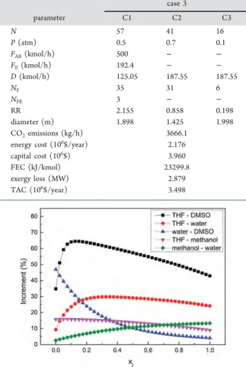
performed. The cost data and design parameters of the optimal design at reduced pressure are shown inTable 2andFigure 8. FromFigure 6, the optimal pressures for C1, C2, and C3 are 0.5, 0.7, and 0.1 atm. The effects of three operating pressures P1, P2, and P3on the process FEC and TAC are similar. With the decrease of P1, for instance, the value of TAC first decreases until the optimal pressure and then increases, while the value of energy cost FEC always decreases. The decrease of FEC is attributed to three advantages of reduced pressure. (1) The entrainer flow rate decreases at lower pressure, as shown inFigure 5, which leads to the reduction of reboiler duties and FEC. (2) The relative volatilities of the five binary systems (THF−DMSO, THF−water, water−DMSO, THF−methanol, and methanol−water) are all increased when operating pressures decrease, as displayed inFigure 7. (3) Low-pressure steam is capable of heating the reboiler of the regeneration column C3 at reduced pressure (case 3 inTable 2), while high-pressure steam is needed for that at atmosphere (case 2 in
Table 1). The trend of decreasing TAC when pressure is higher than its optimal value is due to the saving of FEC, while the trend of increasing TAC when pressure is lower than its optimal value is because of the two penalties caused by
reduced pressure. First, the diameters of the columns at reduced pressure (case 3) increase compared to that at atmosphere (case 2), although the entrainer flow rate and reflux ratios are reduced. Second, the heat exchanger areas of condensers increase due to the decrease of temperature driving force at reduced pressure. In a word, comparing case 3 with Figure 6.Effect of operating pressures P1, P2, and P3on the TAC and
FEC for the total process.
Table 2. Optimal Design for Reduced-Pressure Extractive Distillation case 3 parameter C1 C2 C3 N 57 41 16 P (atm) 0.5 0.7 0.1 FAB(kmol/h) 500 − − FE(kmol/h) 192.4 − − D (kmol/h) 125.05 187.55 187.55 NF 35 31 6 NFE 3 − − RR 2.155 0.858 0.198 diameter (m) 1.898 1.425 1.998 CO2emissions (kg/h) 3666.1
energy cost (106$/year) 2.176
capital cost (106$) 3.960
FEC (kJ/kmol) 23299.8 exergy loss (MW) 2.879 TAC (106$/year) 3.498
Figure 7.Percent increment of relative volatilities from 1 to 0.5 atm for five binary mixtures; j means the first component of the binary mixture.
Figure 8.Simulation setup and optimal reduced-pressure design of THF−methanol−water extractive distillation with DMSO (the design of case 3).
case 2, the two penalties lead to the increase of capital cost by 13.4%, whereas the three advantages result in the decrease of energy cost by 19.6%, which gives a reduction of TAC, CO2 emissions, FEC, and exergy loss by 9.6%, 19.2%, 19.4%, and 23.2%, respectively.
5. DOUBLE-EFFECT HEAT-INTEGRATED EXTRACTIVE DISTILLATION
On the basis of the optimal design of reduced-pressure extractive distillation (case 3), the double-effect heat integration (DEHI) method is considered for further improving energy efficiency and reducing energy cost. The principal of DEHI is to use the heat duty of the condenser(s) to heat the reboiler(s) via adjusting the operating pressure to supply enough temperature driving force so as to save the energy cost and capital cost of one reboiler and reduce the TAC of the total process. In the studied extractive distillation process, there are three condensers and three reboilers, but there is no temperature driving force from any condenser to any reboiler, so the operating pressure has to be elevated to increase the temperature in the condenser(s) to implement the heat integration. Theoretically, there are six possible locations to conduct the DEHI, but not all of them are practical, since the bottom temperature for the high-pressure column should not exceed the temperature of the high-pressure steam.Table 3
shows all the possible configurations for implementing DEHI in a three-column flowsheet.
After several trials, we finally find two potential config-urations for DEHI, as shown in Figure 9: model 1 is to integrate the condenser heat duty of C2 to the reboiler heat duty of C1, and model 2 is to employ the condenser of C3 to heat up the reboiler of C1. In addition, the triple-effect heat integration (TEHI) method (integrating QC2 and QR1 meanwhile integrating QC3 and QR2) is failed because the bottom temperature of C3 would be higher than the upper-limit temperature of high-pressure steam.
5.1. Double-Effect Heat Integration of Model 1. For this configuration, the key parameter is the operating pressure P2 of C2. It is increased to provide the temperature driving force between the condenser of C2 and the reboiler of C1. Meanwhile, the reflux ratio of C2 is adjusted to satisfy the product purity of methanol. There are three possible conditions for the DEHI process: direct partial heat integration (DPHI), direct full heat integration (DFHI), and optimal heat integration (OHI).41The OHI process goes one step further than the DPHI and DFHI processes by optimizing the eight variables (NFE, NF1, NF2, NF3, FE, RR1, RR2, RR3) together via a two-step optimization procedure, but under the minimization of an improved full energy consumption (FEC2), as shown in
eq 6. The meaning of the variables and the value of the factors are the same as insection 2.3.
mQ MQ m Q Q MQ mQ mQ kD D x x x x min FEC2 ( ) /( ) subject to 0.999 0.999 0.999 0.9999 D D D W C1 R2 C2 R1 R3 C3 cooler 1 2 THF, 1 methanol, 2 water, 3 DMSO, 3 = [ + + − + + + ] + ≥ ≥ ≥ ≥ (6) One thing that should be mentioned is that although the optimal design of RPED (case 3) inFigure 8shows that QC2is less than QR1for the studied process, QC2would be higher than QR1after adjusting the operating pressure, because the increase of reflux ratio (RR2) caused by reaching product purity constraints. Therefore, the heat duty required in the bottom of C1 could be totally supplied by part of the heat duty from the top of C2 and there is no need to perform DFHI processes. The results corresponding to selecting the optimal value of P2 for DPHI and OHI designs are displayed inTable 4.
From Table 4, there are two strange but reasonable phenomenons. First, why RR3 and RR2 are increased when only P2 is adjusted from case 4a to case 4f at DPHI configurations? The superficial reason is that the purity of water in C3 could not satisfy the specification, even when all the other design parameters are kept the same as that in case 3. The essential reason is that the feeding temperature of C3 at the DEHI configuration is much higher than that at the RPED configuration, resulting in the decrease of the reboiler heat duty of C3 following the principle of distillation and further the Table 3. All Possible DEHI Configurations for
Three-Column Extractive Distillation Flowsheet
model 1 2 3 4 5 6 cold source QR1 QR1 QR2 QR2 QR3 QR3
heat source QC2 QC3 QC1 QC3 QC1 QC2
comment yes yes no no no no
Figure 9. Sketch for double-effect heat-integrated extractive
subquality product purity in C3. Second, why is the heat duty of the reboiler in C3 (QR3) reduced while the reflux ratio (RR3) is increased? It is because more heat duty is taken into C3 by the feed stream W2(seeFigure 9a) at a higher value of P2, leading to the increase of RR3and the decrease of QR3.
Compared with case 3 inTable 2, cases 4a−4g inTable 4for DEHI configurations perform much better since FEC2, CO2 emissions, exergy loss, and TAC are reduced drastically. Following the increase of P2, energy consumption FEC2 and CO2 emissions increase all the time because increasing P2 would reduce the relative volatility of the studied system, as shown inFigure 7. The exergy loss increase with the increasing of P2is due to the increase of the temperature difference of the integrated heat exchanger. However, TAC first decreases to a minimum value when P2is at its optimal value (2.9 atm) and then increases. The reason is that the ΔT (temperature driving force) for the heat exchanger increases at higher P2 and the heat exchange area (AHI) decreases quickly, leading to the saving of capital cost and TAC. When ΔT is high enough, the benefit of increasing P2 is overwhelmed by its penalty (the decrease of relative volatility and the increase of energy cost
caused by high-pressure steam) and TAC increases. Most importantly, at the optimal value of P2(2.9 atm), case 4g in the OHI condition, gives a further reduction in TAC, FEC2, and CO2 emissions compared to case 4c in the DPHI condition. This demonstrates that the OHI condition could perform better than the DPHI condition for the studied system, which is consistent with the literature.40
5.2. Double-Effect Heat Integration of Model 2. In the DEHI of model 2, the QC3would be employed as heat source for QR1, so the operating pressure (P3) of C3 has to be increased to supply enough temperature driving force between the top of C3 and the bottom of C1. Meanwhile, RR3 is adjusted to overcome the drawback caused by the high pressure and to reach the product purity specification. DPHI is first conducted to find the optimal value of P3by minimizing TAC, and then DFHI and OHI processes are evaluated for comparison. The full energy consumption is amended aseq 7, the meaning of the variables and the value of the factors are also the same as insection 2.3. The effect of P3on the DPHI condition and the results of DFHI and OHI at optimal P3are displayed inTable 5.
Table 4. Key Cost Data of DPHI and OHI for Double-Effect Heat Integration Model 1 Based on RPED Case 3
parameter case 4a case 4b case 4c case 4d case 4e case 4f case 4g condition DPHI DPHI DPHI DPHI DPHI DPHI OHI
P2(atm) 2.6 2.8 2.9 3.0 3.2 3.5 2.9 RR2 1.285 1.310 1.322 1.340 1.371 1.418 1.313 RR3 0.260 0.265 0.268 0.271 0.276 0.283 0.269 QR2(MW) 5.159 5.234 5.271 5.317 5.398 5.519 5.250 QC3(MW) 2.839 2.851 2.857 2.864 2.875 2.891 2.859 QR3(MW) 2.253 2.216 2.214 2.203 2.179 2.145 2.208 Qcooler(MW) 0.657 0.657 0.657 0.657 0.657 0.657 0.661 ΔT (K) 5.7 8.0 9.1 10.1 12.1 15.0 9.1 AHI(m2) 1219.7 869.0 764.0 688.4 574.6 463.5 764.2 QHI(MW) 3.949 3.949 3.949 3.949 3.949 3.949 3.950 QC2(MW) 0.013 0.035 0.046 0.067 0.101 0.154 0.029 QR1(MW) 0 0 0 0 0 0 0 CO2emissions (kg/h) 2678.3 2696.8 2705.8 2718.8 2740.5 3156.0 2696.0 FEC2 (kJ/kmol) 20862.3 20998.5 21067.1 21164.5 21328.4 21572.2 20993.7 exergy loss (MW) 2.099 2.113 2.120 2.130 2.147 2.650 2.118 TAC (106$/year) 3.103 3.071 3.066 3.071 3.09 3.153 3.057
Table 5. Key Cost Data of DPHI, DFHI, and OHI for Double-Effect Heat Integration Model 2 Based on RPED Case 3
parameter case 5a case 5b case 5c case 5d case 5e case 5f case 5g condition DPHI DPHI DPHI DPHI DPHI DFHI OHI
P3(atm) 0.7 0.9 1.0 1.1 1.5 1.0 1.0 RR2 0.858 0.858 0.858 0.858 0.858 0.858 0.855 RR3 0.197 0.197 0.197 0.197 0.197 0.854 0.190 QC2(MW) 3.461 3.461 3.461 3.461 3.461 3.461 3.455 QR2(MW) 3.909 3.909 3.909 3.909 3.909 3.909 3.906 QR3(MW) 3.127 3.218 3.259 3.296 3.427 4.658 3.246 Qcooler(MW) 1.084 1.167 1.204 1.238 1.358 1.204 1.212 ΔT (K) 5.0 11.8 14.7 17.4 26.5 14.7 14.7 AHI(m2) 907.7 381.8 305.4 257.2 167.1 16.4 305.8 QHI(MW) 2.578 2.559 2.550 2.542 2.515 3.949 2.536 QC3(MW) 0 0 0 0 0 0 0 QR1(MW) 1.371 1.391 1.4 1.408 1.435 0 1.404 CO2emissions (kg/h) 3207 3253.7 3274.7 3293.7 3360.2 3396.4 3269.8 FEC3 (kJ/kmol) 20471.5 20764.6 20894.5 21015.6 21435.0 21736.7 20864.5 exergy loss (MW) 2.608 2.648 2.665 2.681 2.737 2.839 2.665 TAC (106$/year) 3.291 3.209 3.204 3.205 3.226 3.331 3.199
M Q Q mQ MQ mQ MQ mQ kD D x x x x min FEC3 ( ) /( ) subject to 0.999 0.999 0.999 0.9999 D D D W R1 C3 C1 R2 C2 R3 cooler 1 2 THF, 1 methanol, 2 water, 3 DMSO, 3 = [ − + + + + + ] + ≥ ≥ ≥ ≥ (7) From Table 5, the DEHI model 2 could also reduce the TAC, FEC3, exergy loss, and CO2emissions compared with RPED (case 3) in Table 2, but it shows a higher TAC value than DEHI model 1 inTable 4, which means that DEHI model 1 is superior to DEHI model 2.
For DPHI processes, FEC and CO2emissions increase with the increase of P3. This is mainly because of the decrease of relative volatility between water and DMSO at high pressure. The exergy loss is also increased with the increasing of P3; this is because the increase of temperature difference of the integrated heat exchanger. TAC first decreases and then increases when P3 increases. This is due to the trade-off between the energy cost and capital cost. When P3is at a lower value, the temperature difference for heat transfer is relatively small (e.g., 5.0 K at 0.7 atm in case 5a), and the heat exchanger area decreases quickly as the temperature driving force increases from a small value, leading to the decrease of capital cost and TAC until the optimal value of P3(1 atm). However, when P3and the temperature difference are high enough, the benefit of increasing the temperature difference is lessened. Meanwhile, the operating cost in the column C3 caused by the increase of operating pressure augments gradually until the benefit of increasing P3is overwhelmed by its penalty, resulting in the increase of TAC.
For the DFHI process named case 5f in Table 5, it is performed on the basis of case 5c through the design specification tool in Aspen Plus by setting the specification of (QR1− QC3) as zero and RR3 as variable. Compared with
case 5c in DPHI condition, the TAC, FEC3, and CO2 emissions of case 5f in the DFHI condition are not saved but enlarged by 3.9%, 4.0%, and 3.7% despite the integrated heat duty increasing by 55%. The reason is that RR3has to be increased to make QC3 increase until (QR1 − QC3) is zero. Meanwhile, the corresponding QR3 has to be increased to supply the energy requirement and the price of the needed steam is higher than that in QR2, which results in the increase of FEC3 and TAC. This result reminds us that it is unsuitable to pursue more heat duty being integrated when considering the DEHI process. Furthermore, there should be optimal heat duty for the DEHI process, which corresponds to the minimum TAC.
The OHI process is one useful way to find the optimal heat duty.40The result for the OHI condition is displayed inTable 5as case 5g. Compared with cases 5a−5f, the TAC, FEC3, and CO2 emissions in case 5g are all decreased and the optimal heat duty is 2.536 MW for the studied process. Again, the OHI condition leads to the best design (lowest TAC).
In summary, DEHI model 1 outperforms DEHI model 2 for RPED design from both economic and environmental views, and the best design is case 4g. Compared with the RPED design (case 3) without heat integration, the TAC, FEC2, and CO2emissions of our best design (case 4g) are cut down by 12.6%, 9.8%, and 26.3%, respectively. In addition, compared with the optimal CED design (case 2), the TAC, FEC2, and CO2emissions of our best design are reduced by 21.0%, 27.3%, and 40.5%, respectively. Compared with the design in the literature (case 1), the TAC, FEC2, and CO2emissions of our best design are decreased by 75.1%, 80.5%, and 84.2%, respectively. The detailed results of the final design flowsheet of case 4g are shown inFigure 10.
6. CONCLUSIONS
In this work, an energy-efficient RPED with heat integration was proposed for the separation of the biazeotropic ternary mixture THF−methanol−water, and we built a systematic approach that involves the selection of entrainer and the determination of operating pressure based on a thermody-namic insight study of residue curve maps and the univolatility Figure 10.Optimal heat integration extractive distillation for THF−methanol−water with DMSO (the design of case 4g).
line, global optimization based on a two-step optimization procedure, and double-effect heat integration to achieve further energy savings.
From the study of thermodynamic insight, three conclusions are obtained: (1) it feasible to simultaneously break the two azeotropes in one extractive column, which is illustrated by the distinction of classes 1.0−1a−m1 and 1.0−1a−m2 based on the general feasibility criterion; (2) DMSO is a much better entrainer for the studied ternary mixture by the prediction of its xplocation, which represents the minimum entrainer usage for breaking the azeotropic points; and (3) reduced pressure, which affects the location of xp, is a better choice.
On the basis of the analysis above, two flowsheets are proposed and optimized by the two-step optimization procedure: conventional extractive distillation (CED) and reduced pressure extractive distillation (RPED). For CED, compared with the literature design, the TAC, FEC, and exergy loss of our optimal CED process (case 2) are decreased by 73%, 69%, and 74.7%. For RPED, the optimal pressures for the three columns are P1= 0.5 atm, P2= 0.7 atm, and P3= 0.1 atm. The three benefits and two penalties of reducing the operating pressure are illustrated. The RPED process exhibits great reductions of TAC, CO2 emissions, exergy loss, and FEC by 9.6%, 19.2%, 23.2%, and 19.4% compared with the CED process.
RPED with a heat integration flowsheet is proposed to further reduce energy consumption. Two new objective functions (FEC2 and FEC3) are defined to conduct optimization. The results showed that the OHI process in the configuration of model 1 performs best in terms of economy. Two strange phenomenons of the increase of RR3 and the decrease of QR3are explained reasonably. The optimal RPED with a heat integration process (case 4g) gives a massive reduction in TAC, energy consumption, exergy loss, and CO2 emissions by 75.2%, 80.5%, 85.8%, and 84.2% compared with the literature design (case 1).
It is worth mentioning that the proposed systematic approach could be widely applied for separating other complex biazeotropic ternary mixtures to recover the valuable resources and pursue sustainable development.
■
ASSOCIATED CONTENT*
S Supporting InformationThe Supporting Information is available free of charge on the
ACS Publications websiteat DOI:10.1021/acs.iecr.8b03123. Economic cost calculation formulas for calculating the total annual cost of the processes (Table S1) and binary interaction parameters for the NRTL model of THF− methanol−water with DMSO (Table S2) (PDF)
■
AUTHOR INFORMATIONCorresponding Authors
*X.Y. e-mail:[email protected]. *J.L. e-mail: [email protected]. ORCID
Jinglian Gu:
0000-0001-8565-3542Xinqiang You:
0000-0002-9361-9931Jun Li:
0000-0003-2392-8322 NotesThe authors declare no competing financial interest.
■
ACKNOWLEDGMENTSThis work was financially supported by the National Natural Science Foundation of China (No. 21573027 to J.L., No. 21706062 to X.Y.).
■
NOMENCLATUREAC condenser heat transfer area (m2) AR reboiler heat transfer area (m2)
AHI heat transfer area for heat-integrated heat exchanger of the DEHI process (m2)
C1 the first column C2 the second column C3 the third column
D1 distillate flow rate of column C1 (kmol/h) D2 distillate flow rate of column C2 (kmol/h) D3 distillate flow rate of column C3 (kmol/h) DEHI double-effect heat integration
DFHI direct full heat integration DPHI direct partial heat integration
FAB flow rate of the original azeotropic mixture (kmol/h) FE flow rate of the entrainer (kmol/h)
FEC full energy consumption for process without heat integration
FEC2 full energy consumption for DEHI model 1 FEC3 full energy consumption for DEHI model 2 N1 number of theoretical stages of column C1 N2 number of theoretical stages of column C2 N3 number of theoretical stages of column C3 NFE feed location of entrainer
NFAB feed location of original azeotropic mixture NF2 feed location of column C2
NF3 feed location of column C3 OHI optimal heat integration P1 pressure of column C1 (atm) P2 pressure of column C2 (atm) P3 pressure of column C3 (atm)
QC1 condenser heat duty of column C1 (MW) QC2 condenser heat duty of column C2 (MW) QC3 condenser heat duty of column C3 (MW) QR1 reboiler heat duty of column C1 (MW) QR2 reboiler heat duty of column C2 (MW) QR3 reboiler heat duty of column C3 (MW)
QHI integrated heat duty for the DEHI process (MW) RR1 reflux ratio of column C1
RR2 reflux ratio of column C2 RR3 reflux ratio of column C3 SQP sequential quadratic programming TAC total annual cost (106$/year) TC1 top temperature of column C1 (K) TC2 top temperature of column C2 (K) TC3 top temperature of column C3 (K) TR1 bottom temperature of column C1 (K) TR2 bottom temperature of column C2 (K) TR3 bottom temperature of column C3 (K) xD1 distillate fraction of column C1 xD2 distillate fraction of column C2 xD3 distillate fraction of column C3 Greek Letters
αi‑j volatility of component i relative to component j
γi activity coefficient of component i
■
REFERENCES(1) Luis, P.; Amelio, A.; Vreysen, S.; Calabro, V.; Van der Bruggen, B. Simulation and environmental evaluation of process design: Distillation vs. hybrid distillation−pervaporation for methanol/ tetrahydrofuran separation. Appl. Energy 2014, 113, 565−575.
(2) Raeva, V. M.; Sazonova, A. Y. Separation of ternary mixtures by extractive distillation with 1,2−ethanediol and glycerol. Chem. Eng.
Res. Des. 2015, 99, 125−131.
(3) Xu, Z.; Ji, J.; Wang, G.; Li, X. Rotating zigzag bed application in extractive distillation process of THF−methanol−water system.
Modern Chem. Ind. 2012, 32, 94−96.
(4) Modla, G. Energy saving methods for the separation of a minimum boiling point azeotrope using an intermediate entrainer.
Energy 2013, 50, 103−109.
(5) Luyben, W. L. Improved design of an extractive distillation system with an intermediate−boiling solvent. Sep. Purif. Technol. 2015, 156, 336−347.
(6) Timoshenko, A. V.; Anokhina, E. A.; Morgunov, A. V.; Rudakov, D. G. Application of the partially thermally coupled distillation flowsheets for the extractive distillation of ternary azeotropic mixtures.
Chem. Eng. Res. Des. 2015, 104, 139−155.
(7) Luyben, W. L. Control comparison of conventional and thermally coupled ternary extractive distillation processes. Chem.
Eng. Res. Des. 2016, 106, 253−262.
(8) Zhao, L.; Lyu, X.; Wang, W.; Shan, J.; Qiu, T. Comparison of heterogeneous azeotropic distillation and extractive distillation methods for ternary azeotrope separation ethanol/toluene/water.
Comput. Chem. Eng. 2017, 100, 27−37.
(9) Zhao, Y.; Zhao, T.; Jia, H.; Zhu, Z.; Wang, Y.; Li, X. Optimization of the composition of mixed entrainer for economic extractive distillation process in view of the separation of tetrahydrofuran/ethanol/water ternary azeotrope. J. Chem. Technol.
Biotechnol. 2017, 92, 2433−2444.
(10) Distillation: Equipment and Processes; Górak, A., Zarko, O., Eds.; Academic Press, 2014.
(11) Smallwood, I. Handbook of Organic Solvent Properties; Butterworth−Heinemann, 2012.
(12) Momoh, S. O. Assessing the Accuracy of Selectivity as a Basis for Solvent Screening in Extractive Distillation Processes. Sep. Sci.
Technol. 1991, 26, 729−742.
(13) Kossack, S.; Kraemer, K.; Gani, R.; Marquardt, W. A systematic synthesis framework for extractive distillation processes. Chem. Eng.
Res. Des. 2008, 86, 781−792.
(14) Rodriguez-Donis, I.; Gerbaud, V.; Joulia, X. Thermodynamic insights on the feasibility of homogeneous batch extractive distillation.; 1. Azeotropic mixtures with a heavy entrainer. Ind. Eng.
Chem. Res. 2009, 48, 3544−3559.
(15) van Dyk, B.; Nieuwoudt, I. Design of Solvents for Extractive Distillation. Ind. Eng. Chem. Res. 2000, 39, 1423−1429.
(16) Medina-Herrera, N.; Grossmann, I. E.; Mannan, M. S.; Jiménez-Gutiérrez, A. An approach for solvent selection in extractive distillation systems including safety considerations. Ind. Eng. Chem.
Res. 2014, 53, 12023−12031.
(17) You, X.; Rodriguez-Donis, I.; Gerbaud, V. Low pressure design for reducing energy cost of extractive distillation for separating diisopropyl ether and isopropyl alcohol. Chem. Eng. Res. Des. 2016,
109, 540−552.
(18) Luyben, W. L. Distillation column pressure selection. Sep. Purif.
Technol. 2016, 168, 62−67.
(19) You, X.; Gu, J.; Peng, C.; Shen, W.; Liu, H. Improved design and optimization for separating azeotropes with heavy component as distillate through energy−saving extractive distillation by varying pressure. Ind. Eng. Chem. Res. 2017, 56, 9156−9166.
(20) An, Y.; Li, W.; Li, Y.; Huang, S.; Ma, J.; Shen, C.; Xu, C. Design/optimization of energy−saving extractive distillation process by combining preconcentration column and extractive distillation column. Chem. Eng. Sci. 2015, 135, 166−178.
(21) De Figueiredo, M. F.; Guedes, B. P.; De Araujo, J. M. M.; Vasconcelos, L. G. S.; Brito, R. P. Optimal Design of Extractive
Distillation Columns−a Systematic Procedure Using a Process Simulator. Chem. Eng. Res. Des. 2011, 89, 341−346.
(22) You, X.; Gu, J.; Peng, C.; Rodriguez-Donis, I.; Liu, H. Optimal design of extractive distillation for acetic acid dehydration with Nmethyl acetamide. Chem. Eng. Process. 2017, 120, 301−316.
(23) García-Herreros, P.; Gómez, J. M.; Gil, I. D.; Rodriguez, G. Optimization of the Design and Operation of an Extractive Distillation System for the Production of Fuel Grade Ethanol Using Glycerol as Entrainer. Ind. Eng. Chem. Res. 2011, 50, 3977−3985.
(24) Leboreiro, J.; Acevedo, J. Processes synthesis and design of distillation sequences using modular simulators: a genetic algorithm framework. Comput. Chem. Eng. 2004, 28, 1223−1236.
(25) Vázquez-Castillo, J. A.; Venegas-Sánchez, J. A.; Segovia-Hernández, J. G.; Hernández-Escoto, H.; Segovia-Hernández, S.; Gutiérrez-Antonio, C.; Briones-Ramírez, A. Design and optimization, using genetic algorithms, of intensified distillation systems for a class of quaternary mixtures. Comput. Chem. Eng. 2009, 33, 1841−1850.
(26) You, X.; Rodriguez-Donis, I.; Gerbaud, V. Investigation of Separation Efficiency Indicator for the Optimization of the Acetone− Methanol Extractive Distillation with Water. Ind. Eng. Chem. Res. 2015, 54, 10863−10875.
(27) You, X.; Gu, J.; Gerbaud, V.; Peng, C.; Liu, H. Optimization of pre−concentration, entrainer recycle and pressure selection for the extractive distillation of acetonitrile−water with ethylene glycol.
Chem. Eng. Sci. 2018, 177, 354−368.
(28) Osuolale, F. N.; Zhang, J. Energy efficiency optimization for distillation column using artificial neural network models. Energy 2016, 106, 562−578.
(29) Li, L.; Tu, Y.; Sun, L.; Hou, Y.; Zhu, M.; Guo, L.; Li, Q.; Tian, Y. Enhanced Efficient Extractive Distillation by Combining Heat− Integrated Technology and Intermediate Heating. Ind. Eng. Chem. Res. 2016, 55, 8837−8847.
(30) Ghuge, P. D.; Mali, N. A.; Joshi, S. S. Comparative Analysis of Extractive and Pressure Swing Distillation for Separation of THF− water Separation. Comput. Chem. Eng. 2017, 103, 188−200.
(31) Knapp, J. P.; Doherty, M. F. Thermal Integration of Homogeneous Azeotropic Distillation Sequences. AIChE J. 1990,
36, 969−984.
(32) Luyben, W. L. Comparison of Extractive Distillation and Pressure−Swing Distillation for Acetone−Methanol Separation. Ind.
Eng. Chem. Res. 2008, 47, 2696−2707.
(33) Agrawal, R.; Fidkowski, Z. T. Are Thermally Coupled Distillation Columns Always Thermodynamically More Efficient for Ternary Distillations? Ind. Eng. Chem. Res. 1998, 37, 3444−3454.
(34) Brito, K. D.; Cordeiro, G. M.; Figueirêdo, M. F.; Vasconcelos, L. G. S.; Brito, R. P. Economic evaluation of energy saving alternatives in extractive distillation process. Comput. Chem. Eng. 2016, 93, 185− 196.
(35) Uwitonze, H.; Hwang, K. S.; Lee, I. A new design method and operation of fully thermally coupled distillation column. Chem. Eng.
Process. 2016, 102, 47−58.
(36) Bravo-Bravo, C.; Segovia-Hernández, J. G.; Gutiérrez-Antonio, C.; Durán, A. L.; Bonilla-Petriciolet, A.; Briones-Ramírez, A. Extractive dividing wall column, design and optimization. Ind. Eng.
Chem. Res. 2010, 49, 3672−3688.
(37) Wu, Y. C.; Hsu, P. H. C.; Chien, I. L. Critical assessment of the energy−saving potential of an extractive dividing−wall column. Ind.
Eng. Chem. Res. 2013, 52, 5384−5399.
(38) Kiss, A. A.; Ignat, R. M. Innovative single step bioethanol dehydration in an extractive dividing−wall column. Sep. Purif. Technol. 2012, 98, 290−297.
(39) Luo, H.; Bildea, C. S.; Kiss, A. A. Novel heat−pump−assisted extractive distillation for bioethanol purification. Ind. Eng. Chem. Res. 2015, 54, 2208−2213.
(40) You, X.; Rodriguez-Donis, I.; Gerbaud, V. Reducing Process Cost and CO2Emissions for Extractive Distillation by Double−effect
Heat Integration and Mechanical Heat Pump. Appl. Energy 2016, 166, 128−140.
(41) Gu, J.; You, X.; Tao, C.; Li, J.; Shen, W.; Li, J. Improved design and optimization for separating tetrahydrofuran−water azeotrope through extractive distillation with and without heat integration by varying pressure. Chem. Eng. Res. Des. 2018, 133, 303−313.
(42) Luyben, W. L.; Chien, I. L. Design and Control of Distillation
Systems for Separating Azeotropes; John Wiley & Sons, 2011.
(43) De Figueiredo, M. F.; Brito, K. D.; Ramos, W. B.; Sales Vasconcelos, L. G. S.; Brito, R. P. Effect of solvent content on the separation and the energy consumption of extractive distillation columns. Chem. Eng. Commun. 2015, 202, 1191−1199.
(44) De Koeijer, G.; Rivero, R. Entropy production and exergy loss in experimental distillation columns. Chem. Eng. Sci. 2003, 58, 1587− 1597.
(45) Suphanit, B.; Bischert, A.; Narataruksa, P. Exergy loss analysis of heat transfer across the wall of the dividing-wall distillation column.
Energy 2007, 32, 2121−2134.
(46) You, X.; Rodriguez-Donis, I.; Gerbaud, V. Improved Design and Efficiency of the Extractive Distillation Process for Acetone− Methanol with Water. Ind. Eng. Chem. Res. 2015, 54, 491−501.
(47) Modla, G. Reactive pressure swing batch distillation by a new double column system. Comput. Chem. Eng. 2011, 35, 2401−2410.
(48) Gerbaud, V.; Rodriguez-Donis, I. Chapter 6. Extractive Distillation. In Distillation: Equipment and Processes; Gorak, A., Olujic, Z., Eds.; Elsevier: Oxford, 2014; p 201.
(49) Lee, J.; Cho, J.; Kim, D. M.; Park, S. Separation of tetrahydrofuran and water using pressure swing distillation: Modeling and optimization. Korean J. Chem. Eng. 2011, 28, 591−596.
(50) Wang, Y.; Cui, P.; Zhang, Z. Heat−Integrated Pressure−Swing-Distillation Process for Separation of Tetrahydrofuran/Methanol with Different Feed Compositions. Ind. Eng. Chem. Res. 2014, 53, 7186− 7194.