Pépite | De la dynamique de bouchons liquides dans les réseaux synthétiques soumis à des forçages cycliques au diagnostic et traitement de maladies respiratoires
167
0
0
Texte intégral
(2) Thèse de Stéphanie Signe Mamba, Université de Lille, 2018. Université de Lille École doctorale ED Régionale SPI 072 Unité de recherche IEMN UMR CNRS 8520. Thèse présentée par Stephanie Signe Mamba Soutenue le 21 février 2018 En vue de l’obtention du grade de docteur de l’Université de Lille. Discipline Electronique Spécialité Micro and Nano-technologies, Acoustics, Telecommunications. Titre de la thèse. De la dynamique de bouchons liquides dans les réseaux synthétiques soumis à des forçages cycliques au diagnostic et traitement de maladies respiratoires Thèse dirigée par. Farzam Zoueshtiagh Baudoin Michael. directeur co-directeur. Composition du jury Rapporteurs. Isabelle Cantat Anne Juel. Examinateurs. Vincent Senez Julien Favier. Directeurs de thèse. Farzam Zoueshtiagh Baudoin Michael. © 2018 Tous droits réservés.. professeur à l’Université de Rennes professeur à l’University of Manchester directeur de recherche au CNRS mcf hdr à l’Aix Marseilles Université professeur à l’Université de Lille professeur à l’Université de Lille. lilliad.univ-lille.fr.
(3) Thèse de Stéphanie Signe Mamba, Université de Lille, 2018. The Université de Lille and the IEMN UMR CNRS 8520 neither endorse nor censure authors’ opinions expressed in the theses: these opinions must be considered to be those of their authors.. © 2018 Tous droits réservés.. lilliad.univ-lille.fr.
(4) Thèse de Stéphanie Signe Mamba, Université de Lille, 2018. Keywords: two phase flow, cyclic forcings, taylor flow, slug, bolus, capillary tube, synthetic networks, airways reopening Mots clés : écoulement diphasiques, forçages périodiques, bouchons liquides, bolus, tubes capillaires, réseaux synthétiques, réouverture des voies respiratoires. © 2018 Tous droits réservés.. lilliad.univ-lille.fr.
(5) Thèse de Stéphanie Signe Mamba, Université de Lille, 2018. v. Life is an experimental journey undertaken involuntarely. Fernando Pessoa Science never solves a problem without creating ten more. George Bernard Shaw It is easier to disintegrate an atom than a prejudice. Albert Einstein. © 2018 Tous droits réservés.. lilliad.univ-lille.fr.
(6) Thèse de Stéphanie Signe Mamba, Université de Lille, 2018. vi. Abstract. The dynamics of liquid plugs in synthetic networks under cyclic forcings: towards understanding and treatment of respiratory diseases Abstract Breathing is one of the most vital mechanism for humans. Indeed, one can live a few days without eating or drinking, but only few minutes without breathing. Owing to the complexity of the respiratory system, the mechanism of breathing is not well understood, especially in pathological conditions when airways are obstructed by mucus. The presence of liquid plugs resulting from the accumulation of mucus in the bronchial tree is a characteristic of genetic diseases like cystic fibrosis or chronic diseases like asthma or chronic bronchitis. Thus, understanding the dynamics of these plugs during the breathing cycle is essential to improve our understanding of those diseases. In this thesis, we study experimentally and theoretically, the dynamics and rupture of liquid plugs under unidirectional and cyclic forcing in a rigid capillary tube. We develop a reduced dimension model, which quantitatively reproduces the observed dynamics, unveil the underlying physics and in particular the sources of the plug instability leading to its rupture. From this model, we are able to derive the critical pressure magnitude required to reopen obstructed pathways. In addition to the study of cylindrical tubes, we investigated the cyclic dynamics of liquid plugs in rectangular channels, a geometry of the utmost interest for microfluidic systems. In this case, we show that under cyclic pressure forcing, two regimes can be observed depending on the values of the capillary number: one leading to the rupture of the plug and one to stable cyclic oscillations. Finally, in the last part of this work, we study experimentally the cyclic forcing of liquid plugs in tree structures mimicking the geometry of intermediate generation of the lung. These preliminary results show that plugs not ruptured during the first half cycle persist in the airways for a long time and oscillate until their rupture. To conclude, we must underline that the initial objective of this thesis was not to achieve a realistic description of pathological flows in the lungs, but only to develop some fundamental solid building blocks that might contribute to this goal in the future. Keywords: two phase flow, cyclic forcings, taylor flow, slug, bolus, capillary tube, synthetic networks, airways reopening. © 2018 Tous droits réservés.. lilliad.univ-lille.fr.
(7) Thèse de Stéphanie Signe Mamba, Université de Lille, 2018. Abstract. vii. De la dynamique de bouchons liquides dans les réseaux synthétiques soumis à des forçages cycliques au diagnostic et traitement de maladies respiratoires Résumé La respiration est un mécanisme essentiel de survie chez les humains. En effet, si nous pouvons survivre quelques jours sans manger et boire, nous ne pouvons survivre que quelques minutes sans respirer. Le système respiratoire est extrêmement complexe de par sa structure fractale qui induit des physiques très différentes entre les voies proximales et distales. Il n’existe à l’heure actuelle aucune modélisation réaliste du système pulmonaire en particulier dans des conditions pathologiques où les voies sont obstruées par des bouchons de mucus. Ces bouchons liquides caractéristiques de certaines maladies comme la mucoviscidose, les bronchites chroniques ou l’asthme résultent de l’accumulation de mucus dans les voies pulmonaires. Comprendre les mécanismes à l’œuvre lors de l’écoulement de ces bouchons lors d’un cycle respiratoire est donc primordial pour améliorer notre compréhension et le traitement de ces pathologies. Nous présentons dans cette thèse une première étude théorique et expérimentale de la dynamique de ces bouchons liquides dans des tubes capillaires rigides soumis à des forçages unidirectionnels et cycliques. Nous avons développé au cours de ce travail un modèle simplifié permettant de reproduire quantitativement les dynamiques observées, de comprendre la physique sous-jacente et en particulier d’identifier les sources d’instabilités qui entraînent la rupture d’un pont liquide. Ce modèle nous a permis de déterminer les pressions critiques nécessaires à la réouverture des voies pulmonaires. Ensuite, nous nous sommes intéressés à la dynamique des ponts liquides dans des tubes rectangulaires, la géométrie la plus communément rencontrée en microfluidique. Dans cette géométrie, nous avons identifié de nouveaux régimes qui n’apparaissent pas dans les géométries cylindriques, et en particulier un régime d’oscillation stable sous forçage en pression périodique. Enfin nous nous sommes intéressés à la dynamique cyclique de ponts liquides dans des réseaux synthétiques en arbres. Nos premiers résultats montrent que les ponts qui ne sont pas détruits lors du premier demi-cycle persistent très longtemps dans les voies et oscillent de manière cyclique dans une génération jusqu’à leur rupture. Pour conclure il est important de souligner que l’objectif initial de cette thèse n’était pas d’aboutir à une modélisation réaliste des écoulements pulmonaires dans des conditions pathologiques, mais simplement d’apporter des briques fondamentales solides qui pourraient y contribuer dans le futur. Mots clés : écoulement diphasiques, forçages périodiques, bouchons liquides, bolus, tubes capillaires, réseaux synthétiques, réouverture des voies respiratoires. IEMN Laboratoire central – Cité scientifique - Avenue Poincaré – CS 60069 – 59652 Villeneuve d Asca Cedex – France. © 2018 Tous droits réservés.. lilliad.univ-lille.fr.
(8) Thèse de Stéphanie Signe Mamba, Université de Lille, 2018. Thanks I wish to express my sincere gratitude to my advisors Michael Baudoin and Farzam Zoueshtiagh for supporting me and for the wise advises they gave me during my journey in the wonderful world of research.. Besides my advisors, I wish to express my gratitude to the committee members for the ideas and feedbacks. The discussions we had, gave me precious clues to improve this work.. A special thank goes to my parents: Signe Louis and Tsimbo Caroline for calling me everyday and encouraging through the most difficult times. I would also like to thank my brothers and sister: Signe Patricia, Signe Guy, Signe Louis, Signe Michel and Signe Arsene for supporting me throughout writing this thesis.. I would like to thank all the members of the AIMAN/FILMS team for the stimulating discussions and particularly for the jokes.. A special thank to Dr. Denis Bitouzé who provided the package Yathesis that was used to write this thesis.. Finally, I would like to thank very warmly some precious friends who contributed in their own way to this achievement: Josephine Fotsing, Barbara Kmer, Ralph Sindjui, Stephane Fotso, Alain Bruno Fadjie, Jean Claude Gerbedoen, Peter Favreau, Maxime seeleuthner, Manon Benedito, Frederic Mebenga, Philemon Nogning, Yvan Ngassa, Christian Kamdem, Cesaire Fotsing, Ottou Thierry.... viii. © 2018 Tous droits réservés.. lilliad.univ-lille.fr.
(9) Thèse de Stéphanie Signe Mamba, Université de Lille, 2018. Thanks. © 2018 Tous droits réservés.. ix. lilliad.univ-lille.fr.
(10) Thèse de Stéphanie Signe Mamba, Université de Lille, 2018. Summary Abstract. vi. Thanks. viii. Summary. x. General introduction Basic features of the mechanism of breathing . . Lung airways: a complex network of capillaries Geometrical description . . . . . . . . . . . Lung airway resistance . . . . . . . . . . . . Mucus . . . . . . . . . . . . . . . . . . . . . Properties . . . . . . . . . . . . . . . Production and transport . . . . . . . Pathologic mucus and lung conditions Pulmonary surfactant . . . . . . . . . . . . Airway closure and reopening models . . . . . . Airway closure . . . . . . . . . . . . . . . . Capillary instability . . . . . . . . . . Elastic collapse . . . . . . . . . . . . . Airway reopening . . . . . . . . . . . . . . . Dissertation plan . . . . . . . . . . . . . . . . . 1 Dynamics of a liquid plug in a capillary tube Abstract . . . . . . . . . . . . . . . . . . . . . 1.1 Introduction . . . . . . . . . . . . . . . . . 1.2 Experimental method and model . . . . . 1.2.1 Experimental setup . . . . . . . . . 1.2.2 Flow rate cyclic driving . . . . . . . 1.2.3 Pressure cyclic driving . . . . . . . 1.2.4 Effects of air compressibility . . . .. . . . . . . .. . . . . . . . . . . . . . . . . . . . . . .. . . . . . . . . . . . . . . . . . . . . . .. . . . . . . . . . . . . . . . . . . . . . .. . . . . . . . . . . . . . . . . . . . . . .. . . . . . . . . . . . . . . . . . . . . . .. . . . . . . . . . . . . . . . . . . . . . .. . . . . . . . . . . . . . . . . . . . . . .. . . . . . . . . . . . . . . . . . . . . . .. . . . . . . . . . . . . . . . . . . . . . .. . . . . . . . . . . . . . . . . . . . . . .. . . . . . . . . . . . . . . . . . . . . . .. . . . . . . . . . . . . . . .. 1 1 4 4 7 8 8 8 10 12 12 12 13 15 16 17. . . . . . . .. 20 20 21 24 25 26 26 28. x. © 2018 Tous droits réservés.. lilliad.univ-lille.fr.
(11) Thèse de Stéphanie Signe Mamba, Université de Lille, 2018. Summary. xi. 1.3 Mathematical model . . . . . . . . . . . . . . . . . . . . . . . . . 1.3.1 Dimensional analysis of the problem . . . . . . . . . . . . 1.3.2 Model: pressure driven forcing . . . . . . . . . . . . . . . . Viscous pressure drop . . . . . . . . . . . . . . . . . . . . . Interfacial pressure drops . . . . . . . . . . . . . . . . . . . Liquid film deposition . . . . . . . . . . . . . . . . . . . . . 1.3.3 Validation of the model for unidirectional pressure forcing in a dry capillary tube . . . . . . . . . . . . . . . . . . . . . . 1.4 Cyclic forcing of liquid plugs . . . . . . . . . . . . . . . . . . . . 1.4.1 Influence of the driving condition: pressure head versus flow rate . . . . . . . . . . . . . . . . . . . . . . . . . . . . . . . 1.4.2 Memory effects and hysteretic behaviour . . . . . . . . . . 1.5 Cyclic motion vs direct rupture of the plug under pressure forcing 1.6 Conclusion . . . . . . . . . . . . . . . . . . . . . . . . . . . . . .. 28 28 30 30 33 37. 2 Critical pressure necessary for airway reopening Abstract . . . . . . . . . . . . . . . . . . . . . . . . . . . . . . . . . . 2.1 Method . . . . . . . . . . . . . . . . . . . . . . . . . . . . . . . . 2.2 Constant unidirectional pressure driving . . . . . . . . . . . . . 2.3 Time dependent unidirectional pressure driving . . . . . . . . . 2.3.1 Transition between different flow regimes . . . . . . . . . . 2.3.2 Influence of the main parameters . . . . . . . . . . . . . . 2.4 Cyclic rectangular pressure driving . . . . . . . . . . . . . . . . . 2.4.1 Flow regimes . . . . . . . . . . . . . . . . . . . . . . . . . . 2.4.2 Stable states . . . . . . . . . . . . . . . . . . . . . . . . . . Physical analysis . . . . . . . . . . . . . . . . . . . . . . . . Analytical description of the stable periodic states . . . . . 2.4.3 Diagram of the flow regimes . . . . . . . . . . . . . . . . . 2.5 Physiologically relevant driving . . . . . . . . . . . . . . . . . . . 2.5.1 Parameters value . . . . . . . . . . . . . . . . . . . . . . . . 2.5.2 Flow regimes of liquid plugs under a realistic breathing cycle 2.5.3 Critical pressure in the airway tree . . . . . . . . . . . . . . 2.6 Assessment of the physiological relevance . . . . . . . . . . . . .. 59 59 60 61 64 65 67 68 68 70 70 71 73 75 75 76 76 78. 3 Dynamics of liquid plugs in rectangular microchannels Abstract . . . . . . . . . . . . . . . . . . . . . . . . . . . . . . . . . 3.1 Introduction . . . . . . . . . . . . . . . . . . . . . . . . . . . . . 3.2 Experimental method . . . . . . . . . . . . . . . . . . . . . . . 3.3 Model of a plug flow . . . . . . . . . . . . . . . . . . . . . . . . 3.3.1 Dimensional analysis and characterisation of the regime 3.3.2 Model of the plug dynamics. . . . . . . . . . . . . . . . .. 80 80 81 82 86 86 88. © 2018 Tous droits réservés.. . . . . . .. 39 42 43 47 51 57. lilliad.univ-lille.fr.
(12) Thèse de Stéphanie Signe Mamba, Université de Lille, 2018. xii. Summary. Viscous pressure drop . . . . . . . . . . . . . . . . . . . . . Front meniscus pressure drop . . . . . . . . . . . . . . . . Rear meniscus pressure drop . . . . . . . . . . . . . . . . . Total pressure drop . . . . . . . . . . . . . . . . . . . . . . Evolution of the plug length . . . . . . . . . . . . . . . . . Static and dynamic wet fraction . . . . . . . . . . . . . . . 3.3.3 Numerical resolution of the equations . . . . . . . . . . . . 3.4 Transition between static and dynamic film deposition . . . . . . 3.4.1 Direct experimental evidence of the transition . . . . . . . 3.4.2 Influence of this transition on the plugs rupture time and rupture length . . . . . . . . . . . . . . . . . . . . . . . . . 3.4.3 Comparison with the dynamics in cylindrical tubes . . . . 3.5 pressure forcings in rectangular microchannels . . . . . . . . . . 3.5.1 Detailed analysis of single plug ruptures. . . . . . . . . . . 3.5.2 Specificity of the cyclic dynamics of liquid plugs in rectangular channels compared to cylindrical channels. . . . . . . . 3.5.3 Evolution of the rupture time and rupture length and comparison between cyclic and unidirectional forcing. . . . . . 3.6 Conclusion . . . . . . . . . . . . . . . . . . . . . . . . . . . . . .. 89 90 92 93 93 94 97 97 97 101 102 102 102 104 109 109. 4 Cyclic dynamics of liquid plugs in networks Abstract . . . . . . . . . . . . . . . . . . . . . . . . . . . . . . . . . . 4.1 Introduction . . . . . . . . . . . . . . . . . . . . . . . . . . . . . . 4.2 Method . . . . . . . . . . . . . . . . . . . . . . . . . . . . . . . . 4.3 Total reopening time and flow regimes in the tree-like networks 4.4 Influence of the network geometry . . . . . . . . . . . . . . . . . 4.5 First pathway reopening time . . . . . . . . . . . . . . . . . . . . 4.6 Volume of reopened airway . . . . . . . . . . . . . . . . . . . . . 4.7 Conclusion . . . . . . . . . . . . . . . . . . . . . . . . . . . . . .. 111 111 112 114 115 117 117 118 121. Conclusion and prospects. 122. Bibliography. 124. Communications. 138. Résumé de la thèse en français 142 Introduction générale . . . . . . . . . . . . . . . . . . . . . . . . . . . 142 Chapitre 1 : Dynamique d’un pont liquide dans un tube capillaire soumis à un forçage cyclique . . . . . . . . . . . . . . . . . . . . . . . 145. © 2018 Tous droits réservés.. lilliad.univ-lille.fr.
(13) Thèse de Stéphanie Signe Mamba, Université de Lille, 2018. Summary Chapitre 2 : Pressions critiques nécessaires à la réouverture des voies respiratoires . . . . . . . . . . . . . . . . . . . . . . . . . . . . . . . . Chapitre 3 : Dynamique d’un pont liquide dans un microcanal rectangulaire soumis à des forçages en pression : Influence de la transition entre le régime de dépôt de film liquide statique et dynamique . . . . Chapitre 4 : Dynamique cycliques des ponts liquides dans des réseaux en arbre . . . . . . . . . . . . . . . . . . . . . . . . . . . . . . . . . . Conclusion . . . . . . . . . . . . . . . . . . . . . . . . . . . . . . . . .. © 2018 Tous droits réservés.. xiii. 148. 150 152 153. lilliad.univ-lille.fr.
(14) Thèse de Stéphanie Signe Mamba, Université de Lille, 2018. General introduction Basic features of the mechanism of breathing The human respiratory system is a biological system made of 3 major parts: (i) the lungs that are pair (left and right lung) of large, air-filled organs found in the thoracic cavity of the chest, (ii) the airways, which include the nose, mouth, pharynx, larynx, trachea, bronchi, and bronchioles and (iii) the muscles of respiration in which the principal role is played by the diaphragm [1]. This (b). (c). Figure 1 – Geometry of the human lung: a) Cast of a human lung. The alveoli have been removed allowing the conducting airways to be seen [2]. b) 3D reconstruction of the first five bronchial generations of a woman lung using computerized tomography for realistic numerical simulations [3]. c) 2D symmetric model of five bronchial generations made of PDMS used for experiments. 1. © 2018 Tous droits réservés.. lilliad.univ-lille.fr.
(15) Thèse de Stéphanie Signe Mamba, Université de Lille, 2018. 2. General introduction. complex system made up of organs, muscles and tissues is essentially used for gas exchange but also plays roles in the metabolization of physiological compounds, filtering the unwanted materials from the circulation, and acts as a reservoir for blood [4, 5]. The process of gas exchange in which oxygen O2 is delivered from the lungs to the bloodstream, and carbon dioxide CO2 is eliminated from the bloodstream to the lungs is only possible by the process of breathing, consisting of repetitive cycles of inspiration and expiration of air from the nose to about 500 millions of small alveoli sacs at a frequency of 12 to 18 breaths per mins [2]. It is therefore a cyclic process that occurs through the lung airways (see Fig. 1). Several factors as the weight, sex, age, activity and the health can affect lung capacity and therefore lung volumes during breathing. Average values of the lung volumes in normal healthy female and male adults are found in Ganong [6]: • The tidal volume (TV): volume of air that moves into and out of the lungs during quiet breathing 0.5l. • The inspiratory Reserve Volume (IRV): additional volume of air that can be forced into the lungs after you breathe in the tidal volume 1.9 − 3.1l. • The expiratory reserve volume (ERV): additional volume of air that be be forced out at the end of a normal expiration 0.7 − 1.2l. • The residual volume (RV): volume of air that remains in your lungs after you force out as much as possible 1.1 − 1.2l. • The total lung capacity (TLC=TV+IRV+ERV+RV): the maximum volume of air that you breathe in and out of your lungs 4.2 − 6l. The mechanism of breathing involves not only the volumes of air that moves in and out of the lung during breathing but also the pressures that are necessary for airflow. Flow of air in the pulmonary airways occurs by bulk flow along pressure gradients created in between the atmosphere and the alveoli (alveolar pressure equal to the atmospheric pressure when there is no airflow). During a quiet breathing, these pressure gradients are created by the contraction of the. © 2018 Tous droits réservés.. lilliad.univ-lille.fr.
(16) Thèse de Stéphanie Signe Mamba, Université de Lille, 2018. Basic features of the mechanism of breathing. 3. diaphragm and the abdominal muscles during inspiration and the elastic recoil of the lungs during expiration (see Fig. 2).. Figure 2 – Mechanics of breathing [2] .. Inspiration is an active process that starts with the contraction of the diaphragm by 1 − 1.5cm which increases the volume of chest by 250 − 350cm3 . This increase in volumes lead to a decrease of the alveolar pressure below the atmospheric pressure (negative pressure) due to Boyle’s law (P V = cst). Bulk flow of air can then occur from places of high pressure (atmosphere) to places of low pressure (lung) until the pressures get equals at the end of the inspiration. Expiration is conversely a passive process in which the muscles of respiration are relaxed because of the elastic recoil of the lung, leading to opposite pressure gradients until the pressure inside the lung and the atmosphere are equal [2]. Simulations of the alveolar pressure using flow resistance models formulation for the respiratory system [7, 8] led to Fig. 3 in which the zero is in reference to the atmospheric pressure. The other functions of breathing include: (i) the physiological regulation, (ii) providing mechanisms for expressions and emotions, (iii) the balance of the nervous-system.. © 2018 Tous droits réservés.. lilliad.univ-lille.fr.
(17) Thèse de Stéphanie Signe Mamba, Université de Lille, 2018. 4. General introduction. Pressure (Pa). 100 50 0 −50 −100 0. 1. 2 Time (s). 3. 4. Figure 3 – Alveolar pressure during a quiet breathing cycle [8] .. Lung airways: a complex network of capillaries Geometrical description Lung airways consist in a network of branching pipes (Fig. 1) that display a broad range of sizes and physical interactions [9]. To fulfill its principal function of mass transport to and from the body, lungs adopt a tree like structure. This configuration is suitable for a minimal volume (about (5 − 6)l in adult), but a very large interface at its extremity for diffusional gas exchange between air and blood (about (70 − 100m2 )) [9, 10, 11, 12, 2]. There are more than 20 generations of branching in the lungs [10, 13, 14]. This complex network can be divided into two main regions (see Fig. 4): • The conducting airways (generations 0–16): consisting of the trachea, the bronchi and the bronchioles. This system of connected ducts acts as low work air conduits, bringing air to the respiratory region. • The respiratory or gas-exchanging region (generations 17-23): In this region, the diameter of the ducts is less than 0.6mm and alveoli start to appear in bronchioles. The number of alveoli increases as it goes further down to the lung and forms at the end section of the airways (generation 23) a clusters where gas-exchange with the blood vessels occurs by diffusion.. © 2018 Tous droits réservés.. lilliad.univ-lille.fr.
(18) Thèse de Stéphanie Signe Mamba, Université de Lille, 2018. Lung airways: a complex network of capillaries. 5. Figure 4 – Ideal model of the human airways adapted by [2] from [15]. The lung airway walls are made of elastic fibers of thickness about 10% their radius with a Young’s modulus E = 6.103 P a and a Poisson’s ratio ν = 0.49 [16] leading to a very flexible material. However, variations in the physical properties the airways generations are found. While the trachea and bronchi have cartilaginous walls, those disappear in the bronchioles and alveoli where they are replaced by smooth muscles [1]. The most commonly used model of lung airways geometry is derived from measurements made by Weibel [10] from which he constructed a symmetrical model using means measurements of the airways tree in which all the airways in a generation are identical and divide dichotomously (see Fig. 4). Another model less used but more complete was proposed by Horsfield [17, 13, 14], who gave a full description of an asymmetric lung by measuring the lengths, diameters and the branching angle in all the generations on a cast of a male lung. He found quite similar values to the one of Weibel except that he counted 24 instead of 23 generations proposed by Weibel and found a number of terminal bronchioles less than half the predictions of Weibel which correspond to only one generation of dichotomous branching. Despite these discrepancies, the model of Weibel is still the most widely used since it offers a mathematical description of the evolution of the generations of the airways. Table 1 present values of this model. © 2018 Tous droits réservés.. lilliad.univ-lille.fr.
(19) Thèse de Stéphanie Signe Mamba, Université de Lille, 2018. 6. General introduction. as well as Reynolds number (Re = ρV l/µ) associated with flows during a quiet breathing (0.5l/s) and vigorous breathing (2l/s) as reported by Pedley [9].. Generation. Diameter d(cm). Length L(cm). Number of alveoli(105 ). Re. Trachea 1 2 3 4 5 10 15 20. 1.8 1.22 0.83 0.56 0.45 0.35 0.13 0.066 0.045. 12 4.76 1.9 0.76 1.27 1.07 0.46 0.2 0.083. 0 0 0 0 0 0 0 0 210. 2325-9300 1719-6876 1281-5124 921-3684 594-2376 369-1476 32-127 1.9-7.6 0.09-0.37. Table 1 – Characteristics of the airway tree and Reynolds numbers associate with two flow velocities in the airway [10, 9].. The flow in the trachea is turbulent and becomes more laminar as we go further in the bronchial tree leading to different physical interactions and therefore different models to study the airflow [12]. Using the data of this model, the characteristics of a typical symmetrical bifurcation in the respiratory region reported in [9, 18] was found to be: diameter ratio between daughter and mother branch dn /dn+1 ∼ 0.79, length to diameter ratio in a generation L/d = 3.5 allowing the construction of a fractal branching tree [19]. As for the mean branching angles α, they are obtained from the data of Horsfield [17] and lie between 64° in airways of diameter greater than 0.4cm to 100° in airways of diameter less than 0.1cm. It is worth mentioning that maximal physical efficiency cannot be the only criterion in the design of a bronchial tree since it is shown by Mauroy & al. [20] that an optimized fractal bronchial tree may be dangerous. This can explain the natural asymmetry of the lung where the right lung is bigger than the left one which shares space with the heart. This asymmetry propagates in the bronchial distribution creating a safety margin while keeping the physiological robustness of the lung.. © 2018 Tous droits réservés.. lilliad.univ-lille.fr.
(20) Thèse de Stéphanie Signe Mamba, Université de Lille, 2018. Lung airways: a complex network of capillaries. 7. Lung airway resistance Airway resistance R is the force opposing air flow in the airway and can be expressed analogously to Ohm’s Law as the pressure difference between the alveoli and the mouth or the nose, ∆P , per unit of airflow Q. R=. ∆P Q. (1). Since the lung airways consist in connected cylindrical pipes, the pressure difference can be expressed in terms of Poiseuille’s law (in generations where the flow is laminar): 128µLQ (2) πd 4 With µ the dynamic viscosity, L and d respectively the length and diameter of a pipe. Therefore, the airways resistance can be expressed in terms of the diameter of the pipe: ∆P =. R=. 128µL πd 4. (3). This simple estimation of the airways resistance shows that if the diameter of the airway is halved for example as a result of asthma [21, 22] or airway obstruction by mucus [23, 24], the resistance will increase by a factor 16. In this case, the respiratory muscles will need to generate much more pressure to overcome this resistance and produce adequate airflow. Thus, diseases affecting the respiratory tract can increase dramatically airway resistance. However, most airway resistance resides in the upper airways (80%) compared to less that 20% in the airways of diameter less than 2mm which is rather counter-intuitive if we assume Poiseuille’s law. This can be explained by the dichotomous division at each generation leading to a rapid increase of the number of bronchi and as a consequence, an increase of the total cross sectional area when we go further in the bronchial tree, thus reducing a lot the total resistance contribution of that region [2].. © 2018 Tous droits réservés.. lilliad.univ-lille.fr.
(21) Thèse de Stéphanie Signe Mamba, Université de Lille, 2018. 8. General introduction. Mucus The human lungs secrete a liquid known as the mucus which coats the airway walls and protects it against foreign material. This protection is essential since millions of particles flow through the airways every day [25]. These particles can be dangerous if they are in contact with the airways wall or pass through the blood system. The role of the mucus is to trap these particles and with the help of the airways cilia, move them out of the lung. The mucociliary system therefore represent the first and major protection of the airway [2]. Properties Airway mucus is a non-homogeneous mixture containing glycoproteins ∼ 2%, proteins 1%, lipids 1%, inorganic salt 1%, DNA 0.02% and cellular debris in a watery matrix 95% secreted from the airways [26, 27, 28]. Mucus is a gel layer that has both solid elastic and viscous fluid properties, floating on a Newtonian layer of low viscous fluid. In addition to its viscoelastic properties [29, 30, 31], the non-Newtonian mucus exhibits other properties as Bingham plastic of finite yield stress (∼ 500 − 600dyn.cm−2 ) [32, 33], shear-thinning, and thixotropy [34]. The mucus layer is no uniformly distributed in the airway tree. In the conducting airway, the mucus thickness is on the order of (5 − 10) microns [9, 35], while in the respiratory region, it is approximately (2 − 4%) of the airway radius [36, 37]. The properties of mucus also changes as we go further in the bronchial tree, becoming Newtonian in the respiratory region because the concentration of proteins that are responsible for the non-Newtonian properties of the mucus reduces [18, 12]. This Newtonian mucus is typically characterized by a surface tension σ = 20mN .m−1 , a dynamic viscosity µ = 10−3 kg.m−1 .s−1 and a density ρ = 103 kg.m3 [38, 16]. Production and transport The goblet cells together with the submucosal glands produce the mucus of the conducting airways [39, 40], at a rate of ∼ 10mL/day in a adult normal lung [41]. The mucus that is secreted needs to be transported out of the airways towards the stomach where it is destructed: this is known as mucociliary transport. The. © 2018 Tous droits réservés.. lilliad.univ-lille.fr.
(22) Thèse de Stéphanie Signe Mamba, Université de Lille, 2018. Lung airways: a complex network of capillaries. 9. transport of mucus through the airways is done by the activity of moving cilia [29, 42].. (a). (b). Figure 5 – Mucociliary clearance: (a) 3D representation of the cilia motion in the lung from the Johns Hopkins school of medicine (b) Motion of cilia during their active stroke adapted by [42] from [43] Each ciliated cell has 200 to 300 uniformly spaced cilia of about 6µm in length [44], with a surface density around (5 − 8) cilia/µm2 [45] . The cilia beat in a synchronized, asymmetric, wavelike manner responsible for the net fluid flow [46, 42]. During their active motion, the cilia that are immersed into the Newtonian layer, with only their tips in contact with the mucus layer, propel the mucus at a rate of ∼ 3mm.min−1 [47] out of the airways (see Fig. 5). The coordinate motion of the cilia in the mucus gel create a surface that undulate in a wavelike manner known as metachronal wave [48, 49, 50]. The efficiency of such a system is highly dependent of the rheology of mucus in particular the depth of the Newtonian layer [51, 18, 52, 53]and the motion and interactions between the cilia and the mucus [54, 42]. Cilia are quite numerous in the trachea and large bronchi but their presence reduce as we go further in the bronchial tree, even disappearing in the respiratory region. The mucus clearance in this region is ensured by the mechanism of breathing or by cough allowing to reach speeds up to 200m.s−1 [55]. Cough is especially important when airways have accumulated abnormal amounts of mucus with altered rheological properties [56].. © 2018 Tous droits réservés.. lilliad.univ-lille.fr.
(23) Thèse de Stéphanie Signe Mamba, Université de Lille, 2018. 10. General introduction. Pathologic mucus and lung conditions. (a). (b). (c). . Figure 6 – Lung conditions: (a-b) Mucus production in asthma and COPD. Excess mucus M is seen partially occluding the large airways (arrows) of asthma and COPD patients. The excess mucus could be due to excess synthesis or hypersecretion, or both [26]. (c) Mucus characteristics of some airways diseases [24]. © 2018 Tous droits réservés.. lilliad.univ-lille.fr.
(24) Thèse de Stéphanie Signe Mamba, Université de Lille, 2018. Lung airways: a complex network of capillaries. 11. Healthy mucus is easily cleared by the mucociliary system whereas pathologic mucus often has altered properties such as higher viscosity and elasticity and is less easily cleared [23, 27]. The combination of mucus hypersecretion and impaired mucociliary clearance can cause a persistent accumulation of altered mucus in the airway which in turns can lead to infection and inflammation by providing an environment for microbial growth. Above a critical thickness, the accumulated mucus can form mucus plugs inside the airways (see Fig. 6) and obstruct airflow through the bronchial tree [57]. Some of the major lung conditions associated with pathologic mucus are: (i) Asthma which is a chronic lung disease triggered by allergy or pollution [58, 35, 59, 60], (ii) Cystic fibrosis which is a genetic disorder in which mucus does not clear easily from the airways [61, 62, 28], (iii) Chronic Obstructive Pulmonary Disease (COPD) characterized by a non reversible and progressive breathing limitations [32, 58, 63] and (iv) Lung cancer that affect almost any part of the lung. Air. Figure 7 – Regular dichotomy model of 5 generation of the lung obstructed by a liquid plug. The obstructed pathways become part of the death volume of the lung adapted from [64]. When a mucus plug obstructs a branch of the airway, airflow cannot occur below the plug and the obstructed pathways become part of the death volume of the lung (see Fig. 7). The question of airway reopening is therefore essential for. © 2018 Tous droits réservés.. lilliad.univ-lille.fr.
(25) Thèse de Stéphanie Signe Mamba, Université de Lille, 2018. 12. General introduction. patient suffering from airway obstruction. In the next section, we will see the mechanisms leading to the formation of liquid plugs and show different models of airway reopening.. Pulmonary surfactant Pulmonary surfactant is a mixture of proteins and lipids secreted in the alveoli by the alveolar epithelial type II cells. This material is found in the mucus lining of the alveoli where it acts to decrease surface tension at the air–liquid interface of the alveoli. The presence of surfactant increases the stability of alveoli, although collapse can still occur in disease. It has some other functions including: (i) the reduction of the work necessary to breathe by increasing the pulmonary compliance, (ii) the prevention of the lung collapse and (iii) the lubrication of the lung [2]. A lack of surfactant in the lung result in consequences like the infant respiratory distress syndrome (IRDS) found in premature infants or the respiratory distress syndrome (RDS) in adult, that can even up to death due to the lung collapse. In these cases, surfactant replacement therapy (SRT) can be used to deliver synthetic surfactant bolus into the lung in newborn [65, 66, 67, 68],or surfactant therapy with mechanical ventilator for breathing can be used in adults [69, 70, 68]. The effect of surfactant therapy on mucus was shown to decrease the viscoelasticity of mucus in (RDS) [72], and increase the mucus flow velocities [73, 74]. It can be expected to be beneficial in the treatment of obstructive airway diseases like asthma and chronic bronchitis by enhancing the mucus clearance mechanism (see Fig. 8).. Airway closure and reopening models Airway closure Pulmonary airway closure by liquid (mucus) plugs can occur via various mechanisms including:. © 2018 Tous droits réservés.. lilliad.univ-lille.fr.
(26) Thèse de Stéphanie Signe Mamba, Université de Lille, 2018. Airway closure and reopening models. 13. Plug. Air. Foam. Bubble. Figure 8 – Mucus clearance in a cylindrical bifurcating channel obstructed by a plug of Pig gastric mucin (PGM) mixed with de-ionized water [71]: (a) - (b) Mucus clearance of the mixture using air flow. (c) - (d) Addition of surfactant improved clearing effectiveness due to bubbling in 1mm diameter channels and foaming in 500µm diameter channels. • Surface tension (capillary) instability of the thin liquid film lining the airways [38, 75, 12] • The elastic collapse of the small airways [75, 12, 76, 77] • The introduction of liquid bolus (plugs) in the larger airways during surfactant therapies [78, 68]. Capillary instability The instability leading to the formation of mucus plug is the same mechanism explaining the destabilisation and breakup of a long falling liquid film into small drops of minimal surface area in Fig. 9a, and the formation of liquid plugs in a horizontal tube in Fig. 9b. This phenomenon known as Rayleigh-Plateau instability [80, 81, 82] is caused by capillary, inertia or gravity effects. The situation of a liquid layer lining a tube is the one observed in the lungs, therefore, we will focus on that. A liquid layer lining the walls of a tube is an unstable configuration no matter how smooth the flow is. Lets consider an initial perturbation of wavelength L in. © 2018 Tous droits réservés.. lilliad.univ-lille.fr.
(27) Thèse de Stéphanie Signe Mamba, Université de Lille, 2018. 14. General introduction (a). (b). Figure 9 – Capillary instability of: (a) A water jet film in oil [79]. (b) A liquid film lining an horizontal rigid capillary tube [57].. Figure 10 – Axisymmetric Rayleigh-Plateau instability of a liquid film of thickness h0 lining a tube of radius a. The destabilisation of the liquid layer can eventually lead to the formation of a liquid plug if the wavelength of the perturbation L > 2 π(a − h0 ), or the liquid layer will return to a uniform state if L < 2 π(a − h0 ) [75].. the stream (see Fig 10). Once the instability is initiated, the fluid in the liquid layer continues to distribute until the system reaches a stable configuration minimizing its interfacial energy. The new equilibrium state can eventually lead. © 2018 Tous droits réservés.. lilliad.univ-lille.fr.
(28) Thèse de Stéphanie Signe Mamba, Université de Lille, 2018. Airway closure and reopening models. 15. to the plugs formation if the wave length of the perturbation (L > 2π(a − h0 )). In this situation, the fluid pressure decreases in the cap, driving more fluid in this region and amplifying the perturbation, eventually leading to the formation of a liquid plug. Conversely, if the wave length (L < 2π(a − h0 )), the fluid pressure increases in the cap and a flow occur from the cap to the wall until the fluid returns to an axially stable state. From this analysis, it can be observe that for large wave lengths, a cylindrical interface is always unstable [64, 75]. The development of the Rayleigh-Plateau instability of a liquid film lining a horizontal tube when gravity effect are negligible, result in the competition between viscous and capillary effects. The most unstable mode of the liquid film destabilisation is associate with a characteristic time τrp = 12µa4 /σ h0 3 and √ a wavelength L = 2π 2a [83, 84]. Elastic collapse. (a). (b). (c). (d). Figure 11 – Non-axisymmetric elastic instability of the airway walls[77]: (a) - (b) Two-lobed mode collapse at low liquid surface tension. (c) - (d) Three-lobed mode collapse at high liquid surface tension. The low young modulus of the pulmonary airways make them easy to collapse enhancing the capillary instability of the liquid lining the airways and giving rise to a surface tension capillary-elastic instability (see Fig. 11). Airway closure due to elastic collapse tend to occur naturally in smaller airways of a normal lung at the end of expiration but reopening occurs in the early stage of inspiration [85,. © 2018 Tous droits réservés.. lilliad.univ-lille.fr.
(29) Thèse de Stéphanie Signe Mamba, Université de Lille, 2018. 16. General introduction. 18, 86, 75]. The compression load Pw exerted on the airway wall is proportional to the difference between the external pressure Pe which in this case is the pleural pressure and the pressure in the core of the fluid Pf = Pi − σ /(a − h0 ) with Pi the air pressure in the lumen [75]: Pw = Pe − Pi +. σ (a − h0 ). (4). When surface tension becomes important, the wall pressure increases, leading to the collapse of the airways. At relatively low surface tension, the collapse of the airway is dominated by the external pressure and the two lobed nonaxisymmetric instability occurs. Increasing the surface tension increases the effects of the load caused by the liquid plug. This situation is favorable to generate three lobed non-axisymmetric collapse that is more likely to occur when the airway collapse over a short axial length scale due to a high surface tension [77]. Pathological conditions may give rise to permanent pulmonary collapse by changing the mucus properties or the mechanical properties of the airways. Other studies on the walls elasticity [87, 88, 89], the non-Newtonian properties of mucus [90, 31], the presence of surfactant [91],the effects gravity [92, 93, 57], the curvature of the bronchi [94] or inertia [95] affect the development of the instability.. Airway reopening The issue of airway reopening is critical for patients suffering from airway obstruction. Several models to study airway reopening in rigid tubes under constant pressure difference have been developed in the literature. From these studies, the central role played by the liquid lining the airway is shown: In a dry capillary tube (see Fig. 12), the propagation of the liquid plug is always accelerative since the plug always leaves liquid on the walls and does not recover liquid from its front meniscus (interface), the plug decreases in size and ruptures in an accelerative event [96]. The propagation of the plug in a liquid-lined tube can be either accelerative or decelerative depending on the initial liquid film layer h0 [97, 98]. This ascertainment allowed the derivation of the critical. © 2018 Tous droits réservés.. lilliad.univ-lille.fr.
(30) Thèse de Stéphanie Signe Mamba, Université de Lille, 2018. Dissertation plan. 17. Figure 12 – Rupture of a liquid plug in a rectangular microfluidic channel showing the evolution of the front meniscus (interface) and the rear meniscus (interface) [96]. constant pressure head required to rupture a liquid plug in a liquid-lined tube [97]. Modeling of the propagation of liquid plugs also allowed to determine the mechanical stresses exerted on the walls during the propagation of a liquid plug and therefore quantify the damages on pulmonary airways [99].The effects of gravity and inertia [93] and non-Newtonian properties of the mucus [100] were also explored. In particular, the non-Newtonian properties of the fluid lead to an increase in the pressure drop necessary to drive the flow at a given speed. In addition, walls flexibility was investigated to determine the pressure necessary to reopen obstructed pathways since the walls deform during the liquid plug formation and propagation in the airway tree [103, 104, 102, 105, 106]. In this configuration, the effect of surfactant [107] was shown to increase the normal stresses during reopening and the non-Newtonian properties of the liquid [108] lead to higher reopening driving pressure and longer reopening times (see Fig. 13).. Dissertation plan This study was motivated by the absence of literature on the response of liquid plugs to complex driving conditions. Indeed, nearly all the model experiments. © 2018 Tous droits réservés.. lilliad.univ-lille.fr.
(31) Thèse de Stéphanie Signe Mamba, Université de Lille, 2018. 18. General introduction (a). (c). (e). (b). Re=50. Bo=0.1 ; Re=0. Bo=0.6 ; Re=0. (d). Re=50. Bo=0.6 ; Re=0. (f). Figure 13 – Flow fields during the propagation of a liquid plug in a channel: (a)Steady propagation of a liquid plug at Re = 50 without surfactant [101] (b)Steady propagation of a liquid plug at Re = 50 with surfactant [101]. (c) Effect of gravity (Bo = 0.1; 0.6) in the unsteady propagation of a liquid plug without inertia effects [93]. (d) Effect of gravity (Bo = 0.6) and presence of surfactant in the unsteady propagation of a liquid plug without inertia effects [93]. (e) Model of PDMS channel with only one flexible wall [102]. (f) Propagation of a liquid plug in a flexible tube with only one flexible wall[102].. and simulations are conducted with a constant driving pressure or flow rate, which strongly differs from conditions enforced during a breathing cycle. This work aims at offering an experimental and theoretical understanding of the flow dynamics and rupture of liquid plugs under cyclic laminar forcing at a frequency close to a real breathing cycle. The fluid that is used in the experimental sections of this work is a Newtonian fluid (Perfluorodecalin PFD) of density ρ, surface tension σ and dynamic viscosity µ close to the serous mucus. The experiments are performed in specific conditions: laminar flow (Re < 2000), negligible gravity effects (Bo << 1) and low capillary number (Ca < 10−1 ). These hypothesis are valid below generation 10 of the airways for bronchioles of diameter below 1mm (Table 3.1).. © 2018 Tous droits réservés.. lilliad.univ-lille.fr.
(32) Thèse de Stéphanie Signe Mamba, Université de Lille, 2018. Dissertation plan. 19. In this work, we do not consider the presence of alveoli on the bronchi that are present in the respiratory region, the walls flexibility, the curvature of the bronchi or the presence of surfactant. We also assume that the capillary instability already occurred and the mucus plugs are already formed as in pathological conditions. We thus focus on the effects of cyclic periodic forcings mimicking a breathing cycle (see Fig. 3) on the dynamics of these plugs. Though it is an ideal model, we expect this study to open new prospects in the comprehension of mucus flow in the lung. The first chapter of this dissertation focuses on the periodic flow rate and pressure forcing of liquid plugs in cylindrical rigid capillary tubes. Depending on the type of forcing, different behaviors are observed and the mechanisms leading to the rupture of liquid plugs are explained. In the second chapter we determine the critical pressure magnitude necessary to reopen obstructed prewetted tubes submitted to cyclic forcing. The third chapter investigates periodic forcing of liquid plugs in a rectangular channels. It is shown that the transition between two liquid film deposition regimes due to the polygonal shape of the microfluidic channel dramatically modifies the plug dynamics. And the last chapter explores periodic forcings of liquid plugs in tree-like symmetric and asymmetric networks. Different regimes are observed depending on the amplitude of the forcing and the geometry of the network. The preliminary results show that plugs not ruptured during the first half cycle persist in the airways for a long time and oscillate until their rupture. The first chapter of this thesis was accepted for publication in the Journal of Fluid Mechanics and the third chapter is submitted to the International Journal of Multiphase Flow.. © 2018 Tous droits réservés.. lilliad.univ-lille.fr.
(33) Thèse de Stéphanie Signe Mamba, Université de Lille, 2018. Chapter. 1. Dynamics of a liquid plug in a capillary tube under periodic forcings Abstract In this chapter, we investigate the dynamics of a liquid plug driven by a cyclic periodic forcing inside a cylindrical rigid capillary tube. It is shown that depending on the type of forcing (flow rate or pressure cycle), the dynamics of the liquid plug can either be stable and periodic, or conversely accelerative and eventually leading to the plug rupture. In the latter case, we identify the sources of the instability as: (i) the cyclic diminution of the plug viscous resistance to motion due to the decrease in the plug length and (ii) a cyclic reduction of the plug interfacial resistance due to a lubrication effect. Since the flow is quasi-static and the forcing periodic, this cyclic evolution of the resistances relies on the existence of flow memories stored in the length of the plug and the thickness of the trailing film. Second, we show that contrary to unidirectional pressure forcing, cyclic forcing enables breaking of large plugs in confined space though it requires longer times. All the experimentally observed tendencies are quantitatively recovered from a reduced analytical model. This study not only reveals the underlying physics but also opens up the prospect for the simulation of "breathing" of liquid plugs in complex geometries and the determination of optimal cycles for obstructed airways reopening. 20. © 2018 Tous droits réservés.. lilliad.univ-lille.fr.
(34) Thèse de Stéphanie Signe Mamba, Université de Lille, 2018. 1.1. Introduction. 1.1. 21. Introduction. Since the seminal works on gas-liquid flows in capillary tubes [109], [110] and [111], the subject have attracted much interest among different scientific communities due to their widespread occurrence in many natural and engineered fluidic systems such as pulmonary flows [12], oil extraction [112, 113], flow in porous media [114, 115, 116, 117], or microfluidic systems [118, 119, 120]. In particular, liquid plugs (also called bridges, slugs or boluses) play a fundamental role in pulmonary flows where they can form in healthy subjects [121, 122] or in pathological conditions [123, 124, 125, 126] due to a capillary or elasto-capillary instability [38, 127, 57, 75, 12, 95]. For patients suffering from pulmonary obstructive diseases, these occluding plugs may dramatically alter the distribution of air in the lungs, hence leading to severe breathing difficulties. Conversely, liquid plugs can be used for therapeutic purpose [128, 69]: boluses of surfactant are injected inside the lungs of prematurely born infants to compensate for their lack and improve ventilation [67, 129]. A thorough understanding of liquid plugs dynamics is therefore mandatory to improve both treatments of patients suffering from obstructive pulmonary diseases and of prematurely born infants. When a liquid plug moves inside a cylindrical airway at low capillary number, deformation of the front and rear menisci occurs near the walls and leads to interfacial pressure jumps at the front and rear interfaces. This deformation also leads to the deposition of a liquid film on the walls. From a theoretical point of view, Bretherton [111] was the first to provide an estimation of the pressure jump and the thickness of the liquid layer at asymptotically low capillary numbers. It’s analysis was later formalized in the framework of matched asymptotic expansions [130] who extended this work to higher order developments. Later on, the dynamics of a meniscus moving on a dry capillary tube was studied both experimentally and theoretically [131, 132]. These pioneering results were later extended to unfold the effects of wall elasticity [103], the behavior at larger capillary numbers [133, 134], the effects of surfactants [135], the role of a microscopic or macroscopic precursor film [136, 137], the influence of more complex tube geometries [138, 139, 140], the. © 2018 Tous droits réservés.. lilliad.univ-lille.fr.
(35) Thèse de Stéphanie Signe Mamba, Université de Lille, 2018. 22. CHAPTER 1. Dynamics of a liquid plug in a capillary tube. influence of gravity [92, 93] or the influence of non-Newtonian properties of the liquid [141, 142, 143, 144]. These key ingredients have then been combined with conservation laws determining the evolution of plug size and estimation of pressure jump in the bulk of the plug to provide analytical models of the unsteady dynamics of liquid plugs in capillary tubes [96, 97, 99]. In particular, [96] introduced the long range and short range interactions between plugs to simulate the collective behavior of a train of liquid plugs. These models were in turn used to determine the critical pressure head required to rupture a liquid plug in a compliant [103] or rigid prewetted capillary tube ([97]), or determine the maximum stresses exerted on the walls [99], a fundamental problem for lung injury produced by the presence of liquid plugs in the lung. It is interesting to note that the dynamics of bubbles [111, 145, 146, 147] and liquid plugs in capillary tubes look similar from a theoretical point of view, since the interfacial pressure jumps and the deposition of a liquid film on the walls induced by the dynamical deformation of the interfaces can be calculated with the same formula. Nevertheless, there are also fundamental differences, which lead to very different dynamics: Trains of bubble are pushed by a liquid finger whose viscous resistance to the flow is generally higher than the resistance induced by the presence of the bubble. In this case, a pressure driven flow is stable and the flow rate remains essentially constant over time. In the case of liquid plugs, the resistance of the plugs to motion is higher than the one of the air in front and behind the plug. This leads to an unstable behavior with an acceleration and rupture of the plugs [96] or a deceleration and the obstruction of the airways [97]. From an experimental point of view, Bretherton’s interfacial laws have been extensively verified for different systems (bubbles, liquid fingers, foams, ...). Nevertheless, there have been few attempts to compare the unstable dynamics of single or multiple plugs in capillary tubes to models accounting for the interface and bulk pressure jumps along with mass balance. Baudoin & al. [96] showed that their model was able to qualitatively predict the collective accelerative dynamics of multiple plugs in rectangular microfluidic channels. More recently, Magniez & al. [97] were able to quantitatively reproduce the acceleration and deceleration of a single liquid plug in a prewetted capillary tube. Their model. © 2018 Tous droits réservés.. lilliad.univ-lille.fr.
(36) Thèse de Stéphanie Signe Mamba, Université de Lille, 2018. 1.1. Introduction. 23. further provided the critical pressure below which the plug slows down and thickens whereas above it accelerates and ruptures. These experiments were particularly challenging owing to the complexity of controlling the prewetting film thickness and performing the experiments before the occurrence of RayleighPlateau instability. Huh & al. [148] measured in realistic experiments the injury caused by the motion of liquid plugs on the human airway epithelium deposited at the surface of an engineered microfluidic airway. Later on, Zheng & al. [102] quantified the deformation of the walls induced by the propagation of a liquid plug in a flexible microchannel. Song & al. [149] employed microfluidic techniques to investigate single liquid plug flow in a tree geometry and evidenced the role of the forcing condition on the flow pattern. Finally, Hu & al. [31] studied the rupture of a mucus-like liquid plug in a small microfluidic channel. From a numerical point of view, simulations of liquid plugs in capillary tubes are highly challenging. Indeed, the thin layer of liquid left on the walls requires either adaptive mesh or the use of Boundary Integral Methods to reduce the computational costs. Moreover, the unstable dynamics of the plugs pushed at constant pressure head leads to high variability in the associated characteristic times. Fujioka & al. [150] were the first to provide numerical simulations of the steady dynamics of a liquid plug in a two-dimensional channel. Later on, they studied the effects of surfactants [101], the unsteady propagation [151] in an axisymmetric tube, the effects of gravity [93] the role played by the tube’s flexibility [102] and the motion of Bingham liquid plugs [100]. More recently, Vaughan & al. [152] studied numerically the splitting of a two dimensional liquid plug at an airway bifurcation. In all the aforementioned theoretical, experimental and numerical studies, the liquid plugs are pushed either at constant flow rate or at constant pressure head in a single direction. These driving conditions substantially differ from the one in the lung where liquid plug will experience periodic forcing. In this chapter, we investigate both experimentally and theoretically the response of liquid plugs to cyclic and periodic pressure or flow rate forcing. The experiments are conducted in straight cylindrical glass capillary tubes and compared to an extended theoretical model based on previous developments [96, 97]. It is shown that, depending on the type of forcing (flow rate or pressure cycle), the dynamics. © 2018 Tous droits réservés.. lilliad.univ-lille.fr.
(37) Thèse de Stéphanie Signe Mamba, Université de Lille, 2018. 24. CHAPTER 1. Dynamics of a liquid plug in a capillary tube. of the liquid plug can either be periodic with the reproduction of the same cyclic motion over time, or accelerative eventually leading to the plug rupture. In particular, this study discloses the central hysteretic role played by the liquid film deposition on the plug dynamics. We first describe the experimental setup and the mathematical model. Thirdly, We discuss the effects of different type of forcings: pressure head and flow rate in the dynamical behavior of the liquid plug. Fourthly, we compare the efficiency of cyclic and unidirectional forcings for obstructed airways reopening. Finally, we discuss on the relevance of the proposed model to pulmonary congestion diseases.. 1.2. Experimental method and model. The schematic of the experimental setup is provided in Fig. 1.1a. A perfluorodecalin liquid plug of controlled volume is injected through a needle inside a rigid horizontal cylindrical glass capillary tube (inner radius R = 470 µm). Then, air is blown at low flow rate (Q = 10µl/min) to bring the liquid plug to the center of the channel and stopped manually when the plug reaches the target position. Thus, depending on the size of the liquid plug, the creation step can take up to 10 s. Finally, liquid plugs are moved back and forth with either pressure or flow rate cyclic forcings enforced respectively with a MFCS Fluigent pressure controller or a KdScientific 210 programmable syringe pump. For both pressure driven and flow rate driven experiments, the period of oscillation is fixed at 2T = 4 s3, with T the duration of the motion in one direction. It is important to note that during the first half-cycle, t ∈ [0, T ], the liquid plug moves along a dry capillary tube (see Fig. 1.1b). The motion of the plug leads to the deposition of a trailing film on the walls of thickness hr behind the rear meniscus at position Xr (t). Thus, in the subsequent back and forth motion, the front interface of the liquid plug moves on walls prewetted by a layer of thickness hf (Xf ) (with Xf (t) = Xr (t) + Lp (t) the position of the front meniscus and Lp (t) the plug length) as long as it remains on a portion of the channel already visited by the liquid plug (see Fig. 1.1c) in a previous half-cycle.. © 2018 Tous droits réservés.. lilliad.univ-lille.fr.
(38) Thèse de Stéphanie Signe Mamba, Université de Lille, 2018. 1.2. Experimental method and model. 1.2.1. 25. Experimental setup (a). needle. Plug Or. Glass pretri dish. (b). (c). Liquid plug. Liquid plug. Figure 1.1 – Experimental description: (a) Experimental setup. (b) First half cycle : the liquid plug moves on a dry capillary tube. (c) Following back and forth motions: the liquid plug moves on a prewetted capillary tube. The glass capillary tubes were cleaned prior to the experiments with acetone, isopropanol, dichloromethane and piranha solutions (a mixture of sulfuric acid (H2SO4) and hydrogen peroxide (H2O2)) successively to obtain perfectly wetting surface and prevent dewetting induced by the presence of dust or organic contaminants on the surface. Perfluorodecalin (dynamic viscosity µ = 5.1 × 10⁻³ P a.s, surface tension σ = 19.3 × 10⁻³ N /m and density ρ = 1.9 × 10⁻³ kg/m3 ) was chosen for its good wetting properties and inertness. Experiments are recorded using a Photron SA3 high speed camera mounted on a Z16 Leica Microscope at a frame rate of 125 images per second, a trigger time of 1/3000s and a resolution of 1024 × 64 pixels. To prevent image deformation due to the cylindrical shape of the capillary tube, it is immersed in an index-matching liquid. The image analysis is then performed using ImageJ software and Matlab.. © 2018 Tous droits réservés.. lilliad.univ-lille.fr.
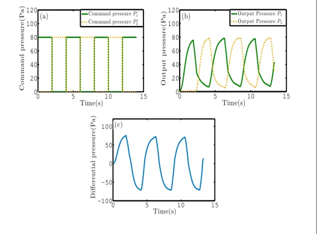
(39) Thèse de Stéphanie Signe Mamba, Université de Lille, 2018. 26. CHAPTER 1. Dynamics of a liquid plug in a capillary tube. 1.2.2. Flow rate cyclic driving. 40. Output flow rate(µl/min). Command flow rate(µl/min). The flow rate forcing (a) is obtained by connecting only one end (left side) of the capillary tube to a programmable syringe pump KdScientific 210. The command flow rate is a square signal with alternative motion in the right and left directions (see Fig. 1.2a). Owing to the response time of the syringe pump and compressibility effects, the actual flow rate imposed to the liquid plug may differ strongly. Thus, the imposed flow rate is monitored directly by measuring the motion of the left interface of the liquid plug. This signal is represented on Fig. 1.2b.. (a). 20 0 −20 −40 0. 5. 10. 15. Time(s). 40. (b). 20 0 −20 −40 0. 5. 10. 15. Time(s). Figure 1.2 – Flow rate cyclic driving: (a) Command flow rate ordered to the programmable syringe pump. Positive values correspond to a motion from the left to the right. (b) Actual flow rate forcing measured by monitoring the motion of the left interface of the plug.. 1.2.3. Pressure cyclic driving. The pressure driving is obtained by connecting two channels of the MFCS programmable pressure controller to both ends of the capillary tube. This pressure controller based on valve and sensors enables automated control of the driving pressure. We impose alternatively a constant command overpressure (compared to atmospheric pressure) P1c and P2c to each channel of the pressure controller while the pressure of the other channel goes down to atmospheric. © 2018 Tous droits réservés.. lilliad.univ-lille.fr.
(40) Thèse de Stéphanie Signe Mamba, Université de Lille, 2018. 1.2. Experimental method and model. 27. 120. Command pressure P 1c Command pressure P 2c. (a) 100. Output pressure(Pa). Command pressure(Pa). pressure, as represented on Fig. 1.3a. Due to the response time of the pressure controller (resulting from the response time of the valve, and the feedback loop, the actual overpressure imposed to each side of the pressure controller (measured by an integrated pressure sensor) is represented on Fig. 1.3b. The final pressure forcing thus corresponds the difference of pressure ∆Pt = P1c − P2c between the two ends of the channel (see Fig. 1.3c).. 80 60 40 20 0 0. 5. 10. 15. 120. Output Pressure P 1 Output Pressure P 2. (b) 100 80 60 40 20 0 0. 5. Differential pressure(Pa). 10. 15. Time(s). Time(s) 100 (c) 50 0 −50 −100 0. 5. 10. 15. Time(s). Figure 1.3 – Pressure cyclic driving: (a) Command pressures P1c and P2c imposed via the software Maesflow to each channel of the MFCS Fluigent pressure controller, connected respectively to each extremity of the capillary tube. (b) Resulting output pressure signals effectively imposed to each end of the capillary tube, measured with an integrated sensor. The pressure represented on these figures correspond to overpressures compared to atmospheric pressure. (c) Pressure driving ∆Pt = P1 − P2 imposed to the liquid plug.. © 2018 Tous droits réservés.. lilliad.univ-lille.fr.
(41) Thèse de Stéphanie Signe Mamba, Université de Lille, 2018. 28. 1.2.4. CHAPTER 1. Dynamics of a liquid plug in a capillary tube. Effects of air compressibility. In the experimental context, compressibility effects are critical for flow rate driven experiments, since they increase the response time of the syringe pump (difference between the piston motion and the actual motion of the fluid in the capillary). To reduce this response time, the syringes are filled with water. Moreover, since the imposed flow rate is measured directly by monitoring the displacement of the left interface, compressibility effects are accounted for in the forcing condition. For pressure driven experiments however, the pressure is homogenised at the speed of sound (extremely rapidly) and the response time is mainly due to the valve and sensors response time. Thus, the pressure measured at the exit of the pressure controller with integrated pressure sensors is almost identical to the pressure imposed at both side of the capillary tube (if we neglect the pressure losses due to the air flow in the tubes compared to the pressure losses due to the presence of the liquid plug).. 1.3 1.3.1. Mathematical model Dimensional analysis of the problem. The characteristic parameters in this problem are the radius of the tube R, the surface tension σ , the liquid density ρ and viscosity µ , and the characteristic speed U of the liquid plug. From these parameters, one can derive the characteristic convection time τc = R/U , the characteristic viscous diffusion time τv = ρR2 /µ, the Reynolds number Re = ρU R/µ (comparing inertia to viscous diffusion), the capillary number Ca = µU /σ (comparing viscous diffusion to surface tension), the Bond number Bo = ∆ρgR2 /σ (comparing gravity effects to surface tension) and finally the Weber number W e = ∆ρU 2 R/σ (comparing inertia to surface tension). Table 1.1 summaries the maximum values of these key dimensionless parameters based on the maximal velocity of the liquid plug Um = 28mm/s observed in the present experiments. Based on the order of magnitude of these dimensionless parameters, a few primary insights can be drawn. The low Bond number and the horizontal. © 2018 Tous droits réservés.. lilliad.univ-lille.fr.
(42) Thèse de Stéphanie Signe Mamba, Université de Lille, 2018. 1.3. Mathematical model. 29. position of the tube suggest weak effect of gravity in this problem. The flow in the bulk of the plug remains laminar owing to the moderate values of the Reynolds number. In addition, Aussillous & Quéré [133] studied the impact of inertia on the deposition of a trailing liquid film behind a moving liquid plug. From dimensional analysis and experiments, they introduced a critical capillary number Cac (equal to 3.6 × 10⁻¹ in the present case) above which the effect of inertia becomes significant. In the present experiments, the capillary number is two order of magnitude smaller than this critical value and thus inertia can be neglected in the film deposition process. Finally, Kreutzer & al. [153] studied numerically the influence of inertia on pressure drops at liquid/air interfaces. They showed that inertia plays no role for Re < 10 at capillary numbers comparable to the present study. Thus, inertial effects can safely be neglected here. Furthermore, the weak capillary and Weber numbers indicate that surface tension is globally dominant over viscous stresses and inertia. Nevertheless, it is to be emphasized that viscous effects must still be accounted for close to the walls, in the so-called "dynamic meniscus" that is the part of the meniscus deformed by viscous stresses. Finally, since the convection and viscous diffusion times τc and τv are two orders of magnitude smaller than the duration of the pressure or flow rate cycles, unsteady term in Navier-Stokes equation can be neglected and the flow can be considered as quasi-static. Another phenomenon that may occur during the plug motion is the destabilisation of the trailing liquid film due to a Rayleigh-Plateau instability. The characteristic time associated with the most unstable mode [83, 84] is given by : τRP =. 12µR4 σ h3. The smallest destabilisation times is thus obtained for the thickest fluid layer. In the experiments conducted in this chapter, the thickness of the liquid film remains typically smaller than 5% of the tube radius leading to τRP = 13 s, whose value remains significantly larger than the period of the plug motion (2T = 4 s). In addition, this time grows rapidly (∝ 1/h3 ) when the thickness of the layer is decreased ( τRP = 58 s for h/R = 3%) and thick films are only deposited close to the plug rupture in the pressure driven experiments so that the destabilisation. © 2018 Tous droits réservés.. lilliad.univ-lille.fr.
(43) Thèse de Stéphanie Signe Mamba, Université de Lille, 2018. 30. CHAPTER 1. Dynamics of a liquid plug in a capillary tube parameters. Formula. Maximum value. τc τv Re Ca Bo We. R/U ρR2 /µ τd /τc µU /σ ∆ρgR2 /σ ∆ρU 2 R/σ. 1.7 × 10⁻² s 8.2 × 10⁻² s 4.9 7.4 × 10⁻³ 2.1 × 10⁻¹ 3.6 × 10⁻². Table 1.1 – Values of the key parameters associated with the maximal velocity Um of the trailing film is expected to play a minor role in the following experiments.. 1.3.2. Model: pressure driven forcing. In this context, the liquid plug dynamics can be predicted from a quasi-static pressure balance and a mass balance. We thus adapted a visco-capillary quasistatic model previously introduced by Magniez & al. [97] to include the motion on both dry and prewetted portions of the tube and also the memory effects resulting from a trailing liquid film deposition. Assuming that the pressure losses in the gas phase are negligible compared to that induced by the liquid plug, the total pressure jump ∆Pt across a liquid plug can be decomposed into int , the sum of the pressure jump induced by the presence of the rear interface ∆Prear bulk the front interface ∆Pfint ront and the flow in the bulk of the plug ∆Pvisc : bulk int ∆Pt = ∆Pvisc + ∆Prear + ∆Pfint ront. (1.1). In the experiments, ∆Pt corresponds to the driving pressure head. Viscous pressure drop Since the flow is laminar, the viscous pressure drop in the bulk of the plug can be estimated from Poiseuille’s law: bulk ∆Pvisc =. © 2018 Tous droits réservés.. 8µLp U R2. (1.2). lilliad.univ-lille.fr.
Figure

![Table 1 – Characteristics of the airway tree and Reynolds numbers associate with two flow velocities in the airway [10, 9].](https://thumb-eu.123doks.com/thumbv2/123doknet/3645215.107477/19.892.190.761.246.499/table-characteristics-airway-reynolds-numbers-associate-velocities-airway.webp)

![Figure 8 – Mucus clearance in a cylindrical bifurcating channel obstructed by a plug of Pig gastric mucin (PGM) mixed with de-ionized water [71]:](https://thumb-eu.123doks.com/thumbv2/123doknet/3645215.107477/26.892.112.739.119.420/figure-clearance-cylindrical-bifurcating-channel-obstructed-gastric-ionized.webp)
+7
![Figure 12 – Rupture of a liquid plug in a rectangular microfluidic channel showing the evolution of the front meniscus (interface) and the rear meniscus (interface) [96].](https://thumb-eu.123doks.com/thumbv2/123doknet/3645215.107477/30.892.110.742.132.396/rupture-rectangular-microfluidic-evolution-meniscus-interface-meniscus-interface.webp)


Documents relatifs