This is an author-deposited version published in:
http://oatao.univ-toulouse.fr/
Eprints ID: 11897
To link to this article: DOI: 10.1260/1756-8293.6.1.29
URL: http://dx.doi.org/10.1260/1756-8293.6.1.29
To cite this version:
Liu, Zhen and Dong, Longlei and Moschetta,
Jean-Marc and Zhao, Jianping and Yan, Guirong Optimization of Nano-Rotor
Blade Airfoil Usinf Controlled Elitist NSGA-II. (2014) International
Journal of Micro Air Vehicles, vol. 6 (n° 1). pp. 29-42. ISSN 1756-8293
O
pen
A
rchive
T
oulouse
A
rchive
O
uverte (
OATAO
)
OATAO is an open access repository that collects the work of Toulouse researchers and
makes it freely available over the web where possible.
Any correspondence concerning this service should be sent to the repository
administrator: [email protected]
Optimization of Nano-Rotor Blade
Airfoil Using Controlled Elitist
NSGA-II
Zhen Liu1a, Longlei Dong1b, Jean-marc Moschetta2c, Jianping Zhao1d
and Guirong Yan1e
1Xi’an Jiaotong University, Xi’an, 710049, China
2Institut Supérieur de l’Aéronautique et de l’Espace, University of Toulouse,
Toulouse 31400, France
ABSTRACT
The aerodynamic performance of airfoil at ultra-low Reynolds number has a great impact on the propulsive performance of nano rotor. Therefore, the optimization of airfoil is necessary before the design of nano rotor. Nano rotor blade airfoil optimization is a multi-objective problem since the airfoil suffers a wide range of Reynolds number which increases the difficulty of optimization. In this paper, the airfoil of nano rotor was optimized based on the controlled elitist Non-dominated Sorting Genetic Algorithm II (NSGA-II) coupling with the parameterization method of Class function/Shape function Transformation technique (CST) and the multi-objectives function processing method of statistical definition of stability. An airfoil was achieved with the thickness of 2% and the maximum camber of 5.6% at 2/3 of chord. Airfoil optimized exhibits a good aerodynamic performance at ultra-low Reynolds number according to the computational results. And comparisons were carried out between the performance of the rotor designed with airfoil optimized and that of the rotor designed with AG38 airfoil, which showed that the airfoil optimized was suitable for rotor design.
NOMENCLATURE
A rotor disk area (swept area), m2 CT rotor thrust coefficient [T/(1/2ρAΩ2R2] CP rotor power coefficient [P/(1/2ρAΩ3R3] FM figure of merit of rotor
Q torque of rotor, N·m
R radius of rotor, m
ρ∞ freestream fluid density, kg/m3
σ blade solidity [Nbc–/(πR)]
T thrust of rotor, N
Ω rotational velocity, rad/s
1. INTRODUCTION
Rotary-wing Nano Air Vehicle (NAV) is a typical configuration for NAV design. The propulsive performance of rotor determines the flight performance of NAV directly. It is therefore necessary to design the rotor so as to obtain an excellent propulsive performance. As the aerodynamic performance of nano rotor blade airfoil remarkably influences nano rotor performance, the airfoil optimization is an important part of rotor design. However, the study of nano rotor airfoil is rarely performed. SAMARAI, a rotary-wing NAV, employed directly AG38 airfoil [1], and the other design of nano rotor selected the existing low-Re airfoil as well [2]. Therefore, the optimization of nano rotor airfoil requires to be carried out.
aLecturer, State Key Laboratory for Strength and Vibration of Mechanical Structures, school of Aerospace, E-mail:[email protected] bAssociate Professor, State Key Laboratory for Strength and Vibration of Mechanical Structures, school of Aerospace, E-mail:[email protected]
cProfessor of Aerodynamics, Department of Aerodynamics, Energetics and Propulsion, E-mail: [email protected] dEngineer, State Key Laboratory for Strength and Vibration of Mechanical Structures, school of Aerospace, E-mail:[email protected] eProfessor, State Key Laboratory for Strength and Vibration of Mechanical Structures, school of Aerospace, E-mail: [email protected]
A typical airfoil optimization includes a selection of aerodynamic solver, a geometry parametric representation of airfoil, a process of objective function and an airfoil optimization method etc. It is a challenge to combine all the parts together to design an excellent airfoil for nano rotor especially because of its special working condition. Firstly, nano rotor optimization requires an efficient and accurate aerodynamic solver at ultra-low Reynolds number. Nano rotor operates at ultra-low Reynolds number lower than 20,000 because of its small dimension. Since the computational resource and time are enormous for an airfoil optimization, an accurate and efficient solver is preferable. The Navier-Stokes solver coupling with grid generation method was utilized in the optimization of airfoil [3-5] in recent years but it requires enormous computational cost. Vortex panel method such as XFOIL is also popular for the airfoil optimization due to its time-saving characteristics with fairly good results at low Reynolds number. Secondly, the optimization of nano rotor blade airfoil is a multi-objective problem because it should achieve an airfoil with excellent aerodynamic performance at different stations of rotor blade. Because nano rotor is usually both tapered and twisted and the relative velocity of blade section is proportional to the distance from the rotational center along the blade, nano rotor blade airfoil suffers Reynolds numbers ranging from 6000 to 16,000. So, the airfoil optimized shall have excellent aerodynamic performance at different Reynolds numbers. Kunz [6] utilized the lift-to-drag as the objective to optimize the rotor blade airfoil separately at two Reynolds numbers. For the single-point optimization, the aerodynamic performance of airfoil may degrade at off-design point. Most optimizations take the value of objectives at design points as objective functions which results in an irregular airfoil form especially for multi-objective optimizations. Some studies utilized multi-point optimization method to take into account several Reynolds number [7]. However, the optimal airfoil was always achieved with corrugated surface. Li and Padula [8] proposed statistical definition of stability method in which the mean value and the standard deviation of objectives to be optimzied at design points are taken as the final objective functions. This method ensures that the result is optimized at each design point and the airfoil form is smooth.
Besides, the geometry parametric representation of airfoil influences the optimization result. Following references [9] and [10], airfoils were generated with small surface waves for multi-point optimization. Analysis revealed that the application of bad parameterization methods and objective functions resulted in those bad results. The geometry representation is necessary before the optimization. Numerous methods [11-16] including the discrete airfoil coordinates method, the Bezier or B-Spline control point representation method, the free form airfoil representation, the polynomial surface representation and the cubic spline control point representation, were devised to numerically represent airfoil geometry. A good parametric method can construct the airfoil curve with only a few variables. The selection of a parameterization technique is an important step for an airfoil optimization. The parameterization based on the B-Spline has advantages of continuous second-order derivative, fewer design parameters to express various airfoil shapes and intuitive definition of initial design space [9]. However, the B-Spline technique generates airfoils with small surface waves for a multi-point optimization. The free-form parameterization method can prevent easy manipulation, but it is lack of intuitive control and has the inherent difficulties when trying to generate airfoil-like shapes. Some special parameterization methods such as Hicks-Henne function [15] and PARSEC [16] were also developed for certain shape optimization. Kulfan [17, 18] proposed the Class function / Shape function Transformation (CST) method which includes class function and shape function to parameterize geometric shape. This method requires fewer variables to represent airfoil and ensures the smoothness of form.
The airfoil optimization method is also a key point for nano rotor blade airfoil optimization. In the past decades, many methods, which are basically divided into two categories: inverse method and direct method, were proposed to get the form of airfoil directly with the flight condition. Selig et al. [19, 20] developed a multi-point inverse method to design airfoil with a conformal mapping. With the development of computational techniques and algorithm method, the direct methods which allow the process of more complicated problems were applied in the airfoil optimization. Kunz and Kroo [21] carried out an optimization of rotary wing blade airfoil at Reynolds number ranging from 2000 to 6000 based on gradient method. Nemec [22] and Burgree [23] utilized gradient-based numerical optimization methods to fulfil the aerodynamic design problem. Alexandron et al. [24] applied the Approximation and Model Management Framework (AMMF), which has the capacity of rapid and early integration of high fidelity nonlinear analyses and experimental results into the multidisciplinary optimization process, in the airfoil optimization. Other methods such as Nelder-Mead [25] and Differential Evolution (DE) [26] were used in the airfoil design as well. A widely used method shall be the Genetic Algorithm
(GA) method [9, 27-30] since it has many merits. Oyama et al. [9] designed an airfoil with the GA method using a two-dimensional Navier-Stokes solver. The maximum lift-to-drag ratio was taken as the objective and the B-spline function was used to parameterize airfoil. Small surface waves were found on the airfoil designed. Jones [10] combined GA method with XFOIL to optimize an airfoil with the objectives of the maximum lift-to-drag ratio and the minimum acoustics. An airfoil was parameterized with the B-spline function. And a high irregular airfoil surface was obtained. Those methods employed either the conventional GA method or the modified GA method. The diversity and fitness can not be guaranteed. The controlled elitist Non-dominated Sorting Genetic Algorithm II (NSGA-II) method proposed by Deb [31], which increases the diversity of population while keeps the elitists in the population, is a potential candidate for the airfoil optimization method.
From the analysis above, it is found that the inverse method and the direct method are widely utilized to get the airfoil for a special case directly. An inverse method allows the velocity distribution to be directly controlled rather than anticipated from geometry perturbations, while a direct method allows the design of airfoil with taking into account multiple disciplines and multiple points. The direct method has more opportunity to get a global optimized solution. Therefore, some researches [32] combines the indirect method and direct method in order to eliminate their disadvantages. However, the increase of computational resource and the capacity of achieving an optimization airfoil are still under discussed. The representation of airfoil and the process of objective functions have a great impact on the airfoil design since they even determine the efficiency and precision of optimization. The airfoil of nano rotor surfers a large scope of Reynolds number so that the airfoil design is a multi-objective optimization. An excellent optimization method coupling with an accurate and efficient aerodynamic solver, an appropriate parameterization method and a processing method of objective functions is necessary to obtain a nano rotor airfoil with excellent aerodynamic performance.
The aerodynamic performance of nano-rotor blade section influences greatly rotor performance. In order to enhance rotor performance, the shape of blade section shall be optimized. To simply the optimization, the blade section of nano rotor was taken as a two dimensional airfoil without taking into account the spanwise flow along the length of the rotor blade from root to tip. In this paper, the airfoil was firstly parameterized with the robust Class function/Shape function Transformation technique (CST). Successively, the accuracy of aerodynamic solver was verified at ultra-low Reynolds number. Then, the objective functions were processed by a method based on the statistical definition of stability. Finally, the airfoil was optimized using the controlled elitist Non-dominated Sorting Genetic Algorithm II (NSGA-II) method to ensure the robustness and diversity of the population. And the aerodynamic performance of airfoil optimized was computed with a two-dimensional (2D) incompressible N-S solver. Comparisons were carried out between the rotor designed with airfoil optimized and that designed with AG38 airfoil.
2. OPTIMIZATION METHODOLOGIES 2.1. Aerodynamic solver
The optimization of airfoil requires a good optimization method as well as an accurate solver. XFOIL [33] is an analytical method whose inviscid formulation is a linear-vorticity stream function panel method. A Karman-Tsien compressibility correction with a solution generated from closely coupled viscous and inviscid methods is incorporated. It employs a two-equation, lagged dissipation, integral boundary layer solution strongly interacted with the incompressible potential flow via the surface transpiration model and an envelope eN transition criterion which allows prediction of separation
bubble. While reduced by eliminating the interactive design and plotting features, as well as modified to create a callable function, the analytic capabilities of XFOIL remain unchanged. As a result, lift, drag and moment coefficients can be obtained for airfoils operating through flight conditions in relatively brief periods of time. XFOIL was widely verified for airfoil study at Reynolds number above 15,000, but it was scarcely studied at ultra-low Reynolds number. Therefore, the ability of XFOIL to predict the aerodynamic characterization of airfoil at ultra-low Reynolds number was validated before the optimization. XFOIL was firstly verified with AG38 airfoil. AG38 airfoil is a thick airfoil with thickness of 7% but a maximum camber of only 2% at 0.355. Youngren et al. [1] studied the aerodynamic characterization of AG38 at low Reynolds number ranging from 15,000 to 60,000 in NASA Langley 2×3 Boundary Layer Tunnel. Taking account of Reynolds number at which NAV flies, AG38 airfoil was studied with XFOIL at Reynolds number of 15,000 and angles of attack ranging from -4° to -8°. Figure 1 shows that the lift coefficient and drag coefficient vary with the angle of attack for
computational results and experimental results. XFOIL predicted the aerodynamic performance well at the whole range of angle of attack. However, the flow separation was predicted earlier since the slope of lift coefficient curve drops slightly at low angles of attack. Accordingly, the value of lift coefficient computed is lower than that from experiments at angles of attack ranging from 2° to 4°, vice verse for drag coefficient. At negative angles of attack lower than -4°, the lift coefficient was under-estimated. One possible reason might be the early estimation of the separation on the upper surface of airfoil. Validation was performed with NACA0006 airfoil at Reynolds number of 6000 as well. Kunz [6] studied the aerodynamic performance of NACA airfoil with INS2D code at low Reynolds number ranging from 2000 to 8000. INS2D code is two-dimensional incompressible Navier-Stokes solver developed by Rogers in which artificial compressibility method is utilized to deal with incompressible flow. This code was validated by Kunz at low Reynolds number. In this validation, NACA0006 airfoil was studied with XFOIL at Reynolds number of 6000 to compare with Kunz’s result calculated with INS2D. Figure 2 shows the comparison between the results calculated by XFOIL and Kunzs’ results. The lift coefficient predicted by XFOIL match well with that predicted by INS2D except at high angle of attack. Once stall appears, XFOIL fails to capture the rapid drop of the lift coefficient at the angle of attack of 5°. But for the drag coefficient, XFOIL predicts higher value than INS2D after stall.
Figure 1. Comparison of computational results with experimental results of AG38 airfoil [1] at Re 15,000.
Figure 2. Comparison between computational results for XFOIL and computation results for INS2D of NACA 0006 airfoil [6] at Re 6000.
In summary, XFOIL can predict lift coefficient and drag coefficient well at Reynolds number ranging from 6000 to 15000 before stall. However, XFOIL predicts the separation earlier. Once attachment appears, lift coefficient is always overestimated.
2.2. Geometry parametric representation
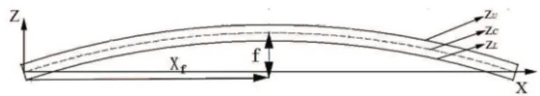
2.2.1. Basic form of blade airfoil
With the development of Micro Air Vehicle, the aerodynamic performance of airfoil at low Reynolds number turns out to be an interesting field. Enormous experiments and computations have been conducted [21, 34-37]. Despite the fact that the airfoil presented in those studies can not be used as the airfoil of nano rotor, they can provide this design with some guidelines. A majority of studies show that the thin plate airfoil exhibits better aerodynamic performance than thick NACA airfoil especially when the thickness is lower than 2% of chord. But conclusions vary each other for the other parameters such as camber, location of camber, leading edge angle and roughness etc. Furthermore, the limitation of traditional fabrication method confines the airfoil form. Consequently, the plate airfoil with thickness of 2% is selected as the basic form (Fig.3). However, the shape of the centreline remains underdetermined. So optimization method was utilized in the following part to obtain the shape of centreline. With the determination of the centreline, the camber and location of maximum camber can be obtained.
Figure 3. Basic form of plate airfoil.
2.2.2. CST representation method
Before the optimization, the airfoil shall be parameterized. Since the plate airfoil was chosen as the basic form, the upper and the lower surfaces of airfoil are able to be represented with the centreline. The selection of the mathematical representation of an airfoil has a profound impact on computational time and resources. It also determines whether the geometries obtained in the design space are smooth and physically realistic. It affects the suitability of the selected optimization process. Therefore, the geometric representation technique shall have the characteristics of being capable of producing smooth and realistic shapes, good mathematical efficiency, good numerical stability, good flexibility and good robustness. After the examination of several different geometry parametric representation methods, it was found the CST representation methodology has a powerful capability to represent a wide variety of 2-D and 3-D geometries encompassing a very large design space with a relatively few scalar parameters. CST method is therefore utilized as the geometry parametric representation. For the upper and the lower surfaces, CST functions are
(1)
and
(2)
where CN1
N2 is the class function, c is the chord length, Aris the weight of each Bernstein polynomial
item, Kris the Binominal coefficient and ∆ZTEis the trailing edge thickness.
Plate airfoil can then be parameterized by the methodology proposed above. To ensure the smoothness of the curve, all the coefficients of Bernstein Polynomial were assumed to be positive. Since the curves of airfoil surfaces are simple, the Bernstein Polynomial is simplified to contain four
z
x
c
C
x
c
A
K
x
c
x
c
x
c
z
c
1
L N N L r r n r n r n r LTE , 1 , 0 2 1∑
=
⋅
−
+ ⋅
∆
+ = −z
x
c
C
x
c
A
K
x
c
x
c
x
c
z
c
1
U N N U r r n r n r n r UTE , 1 , 0 2 1∑
=
⋅
−
+ ⋅
∆
+ = −items. Therefore, there are six parameters to be determined which are (N1,N2,A1,A2,A3,A4). To ensue that the airfoil is physically realistic or acceptable, the bounder of array was constrained in a small zone to reduce the computational time and resource. Since all the parameters are positive, the lower bound and the upper bound were defined to ensure that the equations can cover a wide range of airfoil shape. The results of representation method showed that the airfoil camber varied from 0% to 100% of chord length and the location of camber varied from 0% to 100% of chord length with the bound defined. And it was found that the value of exponents N1and N2defines the basic geometry of airfoil, while A1,A2,A3
and A4 determine the camber and the location of maximum camber. Considering the limitation of computational solver, the leading edge and the trailing edge of airfoil were modified slightly.
2.3. Objective function definition method
Prior to the procedure of optimization, the objective functions shall be determined. Through the analysis of modern MAVs, it is found that one of the bottlenecks of design is the power efficiency during the flight, especially with the drop of the flight speed and the decrease of flight vehicle size. Hovering performance is therefore an important parameters to judge the performance of NAV. Therefore, it shall be paid more attention during NAV design. To characterize the hovering performance, FM is defined as shown in the following equation
(3)
where the thrust coefficient CTis defined as T/[1/2ρ∞A(ΩR)2and the power coefficient C
Pis defined
as P/[1/2ρ∞AΩ3R3].
According to the blade element theory [38], the thrust coefficient is expressed as
(4)
So, the thrust coefficient is the function of the lift coefficient of airfoil. And the power coefficient is written based on the blade element theory [38] as
(5)
From Eq. (5), it is found that the power coefficient is determined by Cl3/2and C
d. Taking account of Eq.
(3), it is found that FM is a function of Cl3/2/C
d of the airfoil. Therefore, the objective of this
optimization is to obtain the maximum value of Cl3/2/C
dof airfoil with the constraint of minimum lift
coefficient. However, the flow condition suffered by airfoil varies along the blade.
The flow condition suffered by airfoil varies along the blade. Thereafter, the optimization is a multi-objective problem to achieve an airfoil with excellent aerodynamic performance at different stations along rotor blade. Several Reynolds numbers can be treated as the design points since Reynolds number varies along the rotor blade. Taking into account the hub of nano rotor, the range of Reynolds number was defined from 6000 to 16,000. Six design points were chosen to optimize the airfoil with equal interval. At each design point, the angle of attack increases from -2° to 10° to search for the maximum
Cl3/2/C
dwith the lift coefficient greater than a specified value Cl,spe.
A method based on the statistical definition of stability [8] was utilized in the present study to process objectives. The objective to obtain a maximum value of Cl3/2/C
d for this optimization was
transformed to obtain a minimum value of Cd /Cl3/2 to be able to apply the method. The mean and
variance of Cd/Cl3/2with respect to Reynolds number are two objective functions defined as,
C 1 C C r C r dr 2 ( 2 ) P T l d 2 3 0 1
∫
σ = + C 1 C r dr 2 T l 2 0 1∫
σ = FM P P C C = ideal T P / 2 3 2 =(6)
where D is the array of design variables after airfoil parameterization and belongs to the design space
X.
2.4. Optimization method
GA is an optimization algorithm based on Darwin’s survival of the fittest evolutionary concept, according to which a biological population evolves over generations to adapt to the environment by the selection, recombination and mutation. It was originally described by Holland in 1960s [39]. Since then, GA was well-developed by Holland and his student, namely Goldberg. With the first application of GA to the practice by Goldberg [40], it has been increasingly applied to engineering design and optimization problems. The Aerodynamic shape optimization as one of important issues of aerodynamic study profits the development of GA in recent years. The aerodynamic shape optimization of rotor airfoil is a multi-variable and multi-objective problem. GA method can solve this problem robustly and achieve a global optimum. For multi-objective optimization, GA finds a local Pareto front for multiple objective functions. The fitness and diversity of population are two criterions to judge the optimal population. The controlled elitist Non-dominated Sorting Genetic Algorithm II (NSGA-II) [31] was therefore applied in the study. NSGA-II applies an elite preserving mechanism and a fast non-dominated sorting procedure. The elimination of tuneable parameter increases the independence of the method to user. However, the elite solutions are composed of all solutions belonging to the currently best non-dominated front. A situation which might occur is that not enough new decision variables can be accepted in new population due to the preservation of elitism in previous generation, i.e. the diversity of population is bad. A suboptimal solution set is obtained instead of a global optimal solution. Therefore, the controlled elitist NSGA-II approach was utilized in the design.
2.4.1. NSGA-II
After the determination of objective functions, the process of GA method can be performed. Following reference [31], the genes are defined as the six variables capable of representing the geometry of the airfoil. Each gene is generated randomly with their lower and upper bounds. Each chromosome is composed of six genes, i.e. D0
j= (N 0 1,j, N 0 2,j, A 0 1,j, A 0 2,j, A 0 3,j, A 0 4,j). Initial population G0 = (D0 1, D 0 2 ,..., D 0 j, ..., D 0
N) is generated randomly according to the bound of the design space. The
initial population contained N chromosomes.
The fitness functions are defined based on the objective functions as shown below.
(7)
(8)
In the function, f1max and f
2max are the maximum values estimated for objective functions. With the
initial population, each chromosome is inputted into the XFOIL solver so that the objective functions are calculated and the correspondent fitness function values are achieved as a result. The fitness values for the jth chromosome are represented as F1,jand F2,j. After the determination of all fitness values for each chromosome, the population is sorted based on non-dominated sort method. The fast sort algorithm proposed by Deb [31] is used in this optimization. Thereafter, all the chromosomes in the population are successively ranked with the no-dominated sort. However, there are usually several
F
f
f
D
f
D
f
else
( , Re), ( , Re)
0,
2 2 max 2 2 2 max=
−
<
F
f
f
D
f
D
f
else
( , Re), ( , Re)
0,
1 1 max 1 1 1 max=
−
<
f D E C D C D f D C D C D D XMinmize ( , Re) (min( ( , Re) ( , Re))) Minmize ( , Re) (min( ( , Re) ( , Re)))
subject to: C 0.68 , Re (6000, 16,000) D L D L 1 3/2 2 2 3/2 L σ = = ≥ ∈ ∈
individuals in one front. In order to compare these individuals, the crowding distance function is introduced to find the Euclidian distance between each individual. All the individuals are assigned a crowding distance value. The crowing distance is then calculated based on their objectives. Thus, each individual in the population has two properties that are no-domination rank defined as Prank and crowding distance Dis. The non-dominated sort has a computational complexity of O(MN2) where M
is the number of genes and N is the number of chromosomes.
With the results of sort, a new child population is generated with the binary tournament selection, the recombination and mutation operators. Binary tournament selection has the advantages of high efficiency, translation and scaling invariant and easy realization of parallel evolutionary algorithms [41]. Therefore, the initial population is processed using binary tournament selection. In order to generate the offspring population of initial population, the simulated binary crossover [42, 43] is utilized to continue process the population obtained from the selection. With the population generated by simulated binary crossover, the polynomial mutation [43] is carried out to generate the final child population defined as GC0. However, the child population GC0 is not the next generation parent
population as stated in the other genetic algorithm. The NSGA-II utilizes a combination of parent population G0and its child population GC0obtained in the initial step to carry out the optimization to
ensure elitism.
(9) The fast non-dominated sort is carried out with R as described above. From the first front, the individuals which have high dominance are added to next generation parent population G1until the size
exceeds the total number of chromosome N. G1is the next generation parent population which will be
used to produce the next iteration until convergence. 2.4.2. Controlled elitist NSGA-II
Despite the fact that the mutation can increase the diversity of population, NSGA-II discards the chromosomes in the pareto front with high rank which deteriorates the diversity of population, especially for the case when the population is mostly comprised of currently best non-dominated solutions. Therefore, a controlled elitist non-dominated sorting GA [31] is utilized here. A geometric distribution is introduced as
(10)
where ni, N, r and K are the maximum number of allowed individuals in the ith pareto front, the number
of individuals in the parent population, the reduction rate defined by users and the number of total pareto front, respectively. Because the next parent population has a number of individuals of N, the
formula ensures the summary of nito be N. If niis higher than the number of individuals in ith pareto
front, the extra number will be succeeded to the ni+1until the end of sort. In the end the next generation parent population is generated with high fitness and diversity. The procedures above continue until the stopping criteria.
3. RESULTS AND DISCUSSION
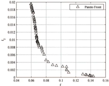
The nano-rotor blade airfoil optimization was carried out at ultra-low Reynolds numbers using the method above. In optimization, the initial population contained 100 individuals and the number of the maximum generation was 200. In order to compute the fitness of each population, XFOIL solver was executed for one hundred times. And in each calculation, the aerodynamic forces of each airfoil shall be computed at several angles of attack. Therefore, the iterations consume huge computational resource. Hereafter, the stop criteria is defined as f1(D,Re)<0.075 and f2(D,Re)<0.075. The stop criteria
was satisfied after 120 generations. The pareto front was shown in Fig.4. The results show good diversity along the pareto front which ensures that the airfoil parameters are well optimized. The airfoil optimized which satisfies the requirement of stop criteria is illustrated in Fig.5. The airfoil has a uniform thickness of 2% with modification at leading edge and trailing edge. The maximum camber is
n
N
r
r
r
1
1
i K i 1=
−
−
− ∪ R=G0 GC05.6% at the location of about 2/3. The camber of airfoil is around 5% from 0.4c to 0.8c which is different from the traditional camber line. However, the airfoil optimized approximates to that designed by Kunz for Mesicopter [6].
Figure 4. Pareto front of airfoil optimization.
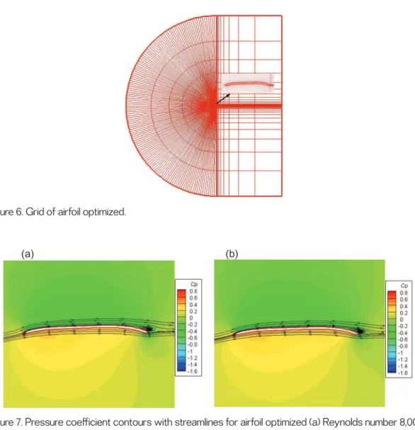
To obtain the accurate aerodynamic performance of airfoil optimized, Computational Fluid Dynamics (CFD) method was used to simulate the flow field. For low-Mach flow, conventional NS equations might fail to converge to a correct solution. Therefore, a two dimensional Incom-pressible Navier-Stokes (INS) solver with artificial compressibility was used to compute the aerodynamic performance of airfoil optimized at ultra-low Reynolds number. Because of the special flight condition of nano rotor, the airfoil suffers flows at a wide range of Reynolds number. The airfoil was simulated at typical Reynolds numbers from 6000 to 16,000 with an interval of 2000. At each Reynolds number, the angle of attack varies with an increment of 2°. The grid of the airfoil was shown in Fig.6. The size of mesh is 161×51 points in the streamwise and the normal direction, respectively. At the leading edge and trailing edge, more grid points were distributed to capture the flow characteristics. The width of the first layer of grid is 10-4 of chord length. The AG38 airfoil was also studied with the same grid
parameter so as to compare with airfoil optimized.
The pressure coefficient contours of airfoil optimized and AG38 airfoil at angle of attack of 4° were presented in Figs.7 and 8. From Fig.7, high pressure was generated on the lower surface of airfoil while lower pressure was generated on the upper surface. And complicate vortices were found at the trailing edge of airfoil, especially at Reynolds number of 16,000. So, unsteady aerodynamic phenomena appear for airfoil optimized at low Re. Slightly separation can be found at the trailing edge. From Fig.8, it was found that the region with high pressure coefficient mainly located at the leading edge and the size of
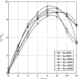
the region is smaller than that of airfoil optimized. Furthermore, the flow on the upper surface of AG38 separated earlier resulting in a large vortex near the trailing edge according to the streamlines when comparing with airfoil optimized. It is evident that airfoil optimized has a better performance than AG38 at ultra-low Reynolds number. Figure 9 illustrates Cl3/2/C
d calculated by INS solver varies with
angle of attack at Reynolds number ranging from 6000 to 16,000 for airfoil optimized. Results show that Cl3/2/C
d increases with the Reynolds number in general but it varies from angle of attack as well.
Generally, it reaches a maximum value at angle of attack of 6°. The maximum Cl3/2/C
d is from 9.5 to
11.2 which are lower than that predicted by the XFOIL. However, they still reach a relatively high value at ultra-low Reynolds number when comparing with other airfoils. The maximum Cl3/2/C
d of airfoil
AG38 is only 7.8 at the Reynolds number of 15,000 and 9.5 at the Reynolds number of 20,000 [1]. The maximum of airfoil NACA0006 at Re 6000 is about 3.9 [6], whereas it is about 9.5 for the airfoil optimized at the same Reynolds number. The lift coefficient of airfoil increases with the increase of Reynolds number while drag coefficient decreases with the increase of Reynolds number, so better aerodynamic performance can be obtained at higher Reynolds number. But the irregular phenomena appear at certain Reynolds number or angle of attack due to the unsteady characteristic of ultra-low Reynolds number flow.
Figure 6. Grid of airfoil optimized.
(a) (b)
Figure 7. Pressure coefficient contours with streamlines for airfoil optimized (a) Reynolds number 8,000 and (b) Reynolds number 16,000.
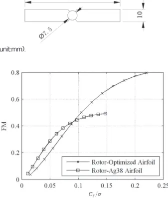
Two rotors with diameter of 75 mm and uniform blade chord length of 10 mm were designed with the airfoil optimized and the AG38 airfoil, respectively, as shown in Fig.10. The rotor blade was designed with uniform chord length and pitch angle from blade root to tip so as to compare only the performance of both rotors influenced by the airfoil. Calculations were performed at 6500 RPM for both rotors while pitch angle varied from 0° to 12° using potential goldstein formulation method. Figure 11 shows the curves that FMs vary with the ratio of thrust coefficient to solidity for both rotors.
It was found that the thrust coefficient reached a higher value for airfoil optimized. Since the solidity is the same for both rotors, the difference of thrust coefficient is caused by the different performance of two airfoils. The FM of rotor designed with AG38 airfoil named as rotor 1 was higher than that of
rotor designed with airfoil optimized named as rotor 2 when the thrust coefficient remained as a small value. However, the FM of rotor 1 increased sharply with thrust coefficient and a maximum value of
about 0.8 was obtained in comparison with only 0.5 for rotor 1. Rotor 2 exhibited a better performance than rotor 1 at high thrust coefficient.
(a) (b)
Figure 8. Pressure coefficient contours with streamlines for Ag38 (a) Reynolds number 8,000 and (b) Reynolds number 16,000.
Figure 9. Cl3/2/C
CONCLUSION
The performance of airfoil has a direct impact on rotor performance. In this paper, nano-rotor blade airfoil optimization was carried out at ultra-low Reynolds number. In order to optimize the airfoil, the parameterization method which has an impact on the efficiency and precision of airfoil optimization was determined firstly. A CST representation algorithm was selected to parameterize the airfoil after a survey of several different representation methods due to its simplicity and robustness. CST can represent current plate airfoil with a few variables and guarantee the continuity and smoothness of the airfoil form. The plate airfoil was represented with six design variables and their bounds were determined. Successively, the flow solver was verified. Because the nano rotor blade airfoil operates at ultra-low Reynolds number and the optimization requires numerous computational resources, the flow solver shall have the capacities of solving the ultra-low-Re flow accurately and efficiently. In this optimization, XFOIL, which is widely verified at low Reynolds number, was used. At several low Reynolds numbers, XFOIL solver was verified with multiple airfoils and the computational results were compared with experimental results and numerical results based on CFD. It is evident that XFOIL can predict the aerodynamic performance of different types of airfoil accurately before the stall. So, it is applicable to use XFOIL as the solver of optimization. Subsequently, the airfoil was optimized. It is innovatively proposed that the objective of this optimization is to obtain the maximum value of Cl3/2/C
d
of airfoil instead of lift-to-drag ratio with the constraint of minimum lift coefficient. Several Reynolds number were chosen as the design points to obtain an excellent airfoil along the blade. The mean and the standard deviation of the objectives at these design points were taken as the objective functions based on the method of the statistical definition of stability. Controlled elitist NSGA-II method was then utilized to design nano rotor airfoil. A plate airfoil with maximum thickness of 2% and maximum camber of 5.6% at 2/3 was achieved. Simulations were carried out using incompressible Navier-Stokes solver which showed that the airfoil optimized had a good aerodynamic performance at ultra-low Reynolds number. And it was found that the airfoil optimized had smaller separation region than AG38 airfoil at ultra-low Reynolds number. When comparing rotors’ performances designed with airfoil optimized and AG38 airfoil, it was found that rotor designed with airfoil optimized can achieve a high
FM and exhibited a better performance at high thrust coefficient, which proved that the optimization
methods are suitable for rotor airfoil design.
In conclusion, the controlled elitist NSGA-II method combining with the CST parameterization
Figure 10. Simple rotor(unit:mm).
method and the statistical definition of stability objective-function-process method was successfully employed in the nano-rotor blade airfoil design. A plate airfoil was designed and exhibited excellent aerodynamic performance at ultra-low Reynolds number.
During the optimization, the spanwise flow along the length of blade from root to tip was not taking into account. Further study shall be performed to take account of it. And the optimization used XFOIL as the aerodynamic solver which predicts the aerodynamic performance of airfoil well at ultra-low Re before stall but fails to predict it after stall. Therefore, other solvers with higher precision and efficiency shall be used in the further study. GA method has the advantages of robustness and independence from initial solutions. However, it requires enormous computational recourses. Therefore, GA method can be used to obtain a solution as the initial solution of the other efficient optimization method.
ACKNOWLEDGEMENTS
The authors would like to thank the support of project 11302164 supported by National Natural Science Foundation of China, project 2012JQ1018 supported by Natural Science Foundation of Shaanxi Province and the Fundamental Research Funds for the Central Universities. They would also like to thank the laboratory of DAEP of ISAE.
REFERENCES
[1] H. Youngren, C. Kroninger, M. Chang and al. et. Low Reynolds number testing of the AG38 airfoil for the SAMARAI nano air vehicle. AIAA Paper, 2008, 417.
[2] R. He and S. Sato. Design of a single-motor nano aerial vehicle with a gearless torque-canceling mechanism. AIAA Paper, 2008, 1417.
[3] M. Secanell and A. Suleman. Sequential optimization algorithms for aerodynamic shape optimization. AIAA Paper, 2004, 4631.
[4] C. H. Sung and J. H. Kwon. Design optimization using the Navier-Stokes and adjoint equations.
AIAA Paper, 2001, 266.
[5] B. I. Soemarwoto. Airfoil optimization using the Navier-Stokes equations by means of the variational method. AIAA Paper, 1998, 2401.
[6] P. J. Kunz. Aerodynamics and design for ultra-low Reynolds number flight [D]. Palo Alto: Stanford University, 2003.
[7] M. Drela. Pros and cons of airfoil optimization. AIAA Paper, 1998.
[8] W. Li and S. Padula. Performance trades study for robust airfoil shape optimization. AIAA Paper,
2003, 3790.
[9] A. Oyama and K. Fujii. Aerodynamic design exploration of flapping wing viewpoint of shape and kinematics. AIAA Paper, 2007, 481.
[10] B. R. Jones, W. A. Crossley and A. S. Lyrintzis. Aerodynamic and aeroacoustic optimization of airfoils via a parallel genetic algorithm. AIAA Paper, 1998, 4811.
[11] J. A. Samareh. Survey of shape parameterization techniques for high-fidelity multidisciplinary shape optimization.AIAA Journal, 39(5), 2001, 877-884.
[12] G. M. Robinson and A. J. Keane. Concise orthogonal representation of supercritical airfoils.
Journal of Aircraft, 38(3), 2001, 580-583.
[13] W. Song and A. J. Keane. A study of shape parameterisation airfoil optimization. AIAA Paper,
2004, 4482.
[14] S. Padula and W. Li. Options for robust airfoil optimization under uncertainty. AIAA Paper, 2002,
5602.
[15] R. M. Hicks and P. A. Henne. Wing design by numerical optimization.Journal of Aircraft, 15,
1978, 407-412.
[16] H. Sobieczky. Parametric airfoils and wings.Notes on Numerical Fluid Mechanic, 68, 1998,
71-88.
[17] B. M. Kulfan and J. E. Bussoletti. Fundamental parametric geometry representations for aircraft component shapes. AIAA Paper, 2006, 6948.
[18] B. M. Kulfan. A universal parametric geometry representation method-CST. AIAA Paper, 2007,
[19] M. S. Selig and M. D. Maughmer. A multi-point inverse airfoil design method based on conformal mapping.AIAA Journal, 30(5), 1992, 1162-1170.
[20] M. S. Selig and M. D. Maughmer. Generalized multipoint inverse airfoil design.AIAA Journal,
30(11), 1992, 2618-2625.
[21] I. Kroo and P. Kunz. Miniature rotorcraft as aerial explorers. USA: ASA/DoD Second Biomorphic Explorers Workshop, 2000.
[22] M. Nemec and M. J. Aftosmis. Aerodynamic shape optimization using a cartesian adjoint method and CAD geometry. AIAA Paper, 2006, 3456.
[23] G. W. Burgree and O. Baysal. Aerodynamic shape optimization using preconditioned conjugate gradient methods.AIAA Journal, 32(11), 1994, 2145-2152.
[24] N. M. Alexandron, E. J. Nielsen, R. M. Lewis and al. et. First-order model management with variable-fidelity physics applied to multi-element airfoil optimization. AIAA Paper, 2000, 4886.
[25] M. Darbandi, A. Setayeshgar and S. Vakili. Modification of standard k-epsilon turbulence model for multi-element airfoil application using optimization technique. AIAA Paper, 2006, 2829.
[26] N. K. Madavan. On improving efficiency of differential evolution for aerodynamic shape optimization applications. AIAA Paper, 2004, 4622.
[27] S. Takahashi, W. Yamazaki and K. Nakahashi. Aerodynamic design exploration of flapping wing viewpoint of shape and kinematics. AIAA Paper, 2007, 481.
[28] Z .Q. Zhu, X. L. Wang, H. Y. Fu and al. et. Aerodynamic optimization design of airfoil and wing.
AIAA Paper, 2004, 4367.
[29] V. Ahuja and A. Hosangadi. Design optimization of complex flowfields using evolutionary algorithms and hybrid unstructured CFD. AIAA Paper, 2005, 4984.
[30] S. Peigin and B. Epstein. 3D optimization of aerodynamic wings based on accurate CFD computations. AIAA Paper, 2005, 454.
[31] K. Deb and T. Goel. Controlled elitist non-dominated sorting genetic algorithms for better convergence. Heidelberg: Springer-Verlag, 2001.
[32] B. A. Gardner and M. S. Selig. Airfoil design using genetic algorithm and an inverse method.
AIAA Paper, 2003, 43.
[33] M. Drela and H. Youngren. XFOIL 6.94 user guide [CP]. MIT Aero and Astro, 2001.
[34] Noriaki. Tsuzuki, Shunichi. Sato and Takashi. Abe. Design guidelines of rotary wings in hover for insect-scale Micro Air Vehicle applications.Journal of Aircraft, 44(1), 2002, 252-263.
[35] S. Sunada, T. Yasuda, K. Yasuda and al. et. Comparison of wing characteristics at an ultralow Reynolds number.Journal of Aircraft, 39(2), 2002, 331-338.
[36] A. Gopalarathnam, B. A. Broughton, B. D. McGranahan and al. et. Design of low Reynolds number airfoils with trips. AIAA Paper, 2001, 2463.
[37] F. Bohorquez, P. Samuel, J. Sirohi and al. et. Design, analysis and hover performance of a rotary wing Micro Air Vehicle.AHS Journal, 48, 2003, 80-90.
[38] J. G. Leishman. Principles of helicopter aerodynamics [M]. 2nd Edition. New York: CambridgeUniv. Press, 2005: 135.
[39] J. H. Holland. Adaptation in natural and artificial system [M]. Boston: MIT Press, 1992. [40] D. E. Goldberg. Genetic algorithms in search, optimization and machine learning [M]. MA:
Addison Wesley Reading, 1989.
[41] D. E. Goldberg and K. Deb. A comparative analysis of selection schemes used in genetic algorithms AIAA Paper, 2001, 69-93.
[42] H. G. Beyer and K. Deb. On self-adaptive features in real-parameter evolutionary algorithm.
IEEE Transactions on Evolutionary Computation, 5(3), 2001, 250-270.
[43] K. Deb and R. B. Agarwal. Simulated binary crossover for continuous search space. Complex System, 9, 1995, 115-148.
![Figure 2. Comparison between computational results for XFOIL and computation results for INS2D of NACA 0006 airfoil [6] at Re 6000.](https://thumb-eu.123doks.com/thumbv2/123doknet/3280923.94142/5.892.269.603.779.1033/figure-comparison-computational-results-xfoil-computation-results-airfoil.webp)