1 INTRODUCTION
Recent events such as natural catastrophes or ter-rorism attacks have highlighted the necessity to en-sure the structural integrity of buildings under an ex-ceptional event. According to the Eurocodes and some different other national design codes, the struc-tural integrity of civil engineering structures should be ensured through appropriate measures but, in most cases, no precise practical guidelines on how to achieve this goal are provided.
The Eurocode dealing with the structural integrity of structures is Eurocode 1, Part 1-7. For the above mentioned reason, this Eurocode is presently under revision with the objective of providing improved general recommendations to ensure an appropriate structural robustness in case of an exceptional event, knowing that the detailed application rules related to specific structural solutions would be reflected in the associated specific Eurocodes, i.e. in Eurocode 2 for concrete structures, in Eurocode 3 for steel struc-tures…
In this framework, the robustness of steel and composite steel-concrete building frames is investi-gated at the University of Liege for many years fol-lowing the so-called “alternative load path method” (Demonceau, 2008, Demonceau & Jaspart, 2010, Demonceau et al, 2011, Comeliau et al, 2012, Hu-velle et al, 2013, HuHu-velle et al, 2015, Demonceau et al, 2017) with the final objective to propose design requirements useful for practitioners to mitigate the
risk of progressive collapse considering the conven-tional scenario “loss of a column” further to an un-specified event.
The present paper gives a global overview of the ongoing researches in the field of robustness at the University of Liège and of the adopted strategy aim-ing at derivaim-ing design requirements to be proposed for future implementation in the Eurocodes. In the following sections, the main outcome of recent re-searches with references to recently published papers will be reflected.
Firstly, the investigations conducted to study the quasi-static response of 2D steel and steel-concrete composite frames subjected to column loss scenarios are introduced in Section 2. Secondly, based on the knowledge gained from the studies presented in Sec-tion 2, the behaviour of 3D structures has been in-vestigated and, in Section 3, it is demonstrated how the developments achieved for 2D frames can be easily extended to predict the behaviour of 3D struc-tures. Finally, the dynamic effects which may be as-sociated to a column loss are considered in Section 4. In particular, it is explained how the dynamic re-sponse of steel and steel-concrete structures can be derived from the quasi-static response.
2 BEHAVIOUR OF 2D FRAMES
When a frame suffers a column loss, two parts can be identified in the structure: the directly affected
Robustness of steel structures subjected to a column loss scenario
J.-F. Demonceau, M. D’Antimo & J.-P. Jaspart
University of Liege, Urban and Environmental Engineering Research Unit, Belgium
ABSTRACT: Recent events such as natural catastrophes or terrorism attacks have highlighted the necessity to ensure the structural integrity of buildings under an exceptional event. According to the modern design codes, the structural integrity of civil engineering structures should be ensured through appropriate measures but, in most cases, no precise practical guidelines on how to achieve this goal are provided. The Eurocode dealing with this topic is Eurocode 1, Part 1-7. For the above mentioned reason, this Eurocode is presently under revi-sion with the objective of providing improved general recommendations to ensure an appropriate structural robustness in case exceptional events. In this framework, the robustness of steel and composite steel-concrete building frames is investigated at the University of Liege for many years following the so-called “alternative load path method”. The present paper gives a global overview of the ongoing researches in the field of robust-ness at the University of Liège.
part and the indirectly affected (Figure 1). The di-rectly affected part contains all the beams, columns and beam-to-column joints located above the lost column. The rest of the structure (i.e. the lateral parts and the storeys under the lost column) is defined as the indirectly affected part.
Figure 1. Behaviour of a 2D frame further to a column loss (Huvelle et al, 2015)
For a frame losing one of its columns (column AB in Figure 1), the evolution of the compression force NAB in the lost member vs. its vertical
shorten-ing (u) can be divided in 3 phases as illustrated in Figure 1.
During Phase 1 (from (1) to (2) in Figure 1), the column is “normally” loaded (i.e. the column sup-ports the loads coming from the upper storeys) and its compression load is defined as equal to NAB normal.
Phase 2 (from (2) to (4) in Figure 1) begins when the column loss is initiated. During Phase 2, a plastic mechanism develops progressively in the directly af-fected part. Each change of slope in the curve during this phase corresponds to the development of a new hinge in the directly affected part, until a complete plastic mechanism is reached at point (4) on Figure 1.
Phase 3 (from (4) to (5) in Figure 1) starts when this plastic mechanism is formed: the vertical dis-placement at the top of the column increases signifi-cantly since there is no more “first order” rigidity in the structure. As a result of these large displace-ments, catenary actions are developing in the beams
of the directly affected part, giving a “second-order” stiffness to the structure. The role of the indirectly affected part during Phase 3 is to provide a lateral anchorage to these catenary actions: the stiffer the indirectly affected part is, the more catenary action will develop in the directly affected part. In the ex-treme situation where the indirectly affected part has no lateral stiffness, then catenary action will not de-velop and there will be no Phase 3.
Point (5) is reached with the vanishing of the axial force in the column. On the basis of the displace-ment associated to point (5), one can estimate the de-formation capacities required in the plastic hinges and evaluate the forces in all the structural elements; accordingly, it is possible to check if the structure is sufficiently robust to reach this new state of equilib-rium.
The prediction of the response of the frame during Phase 1 and Phase 2 can be obtained easily while the prediction the response during Phase 3 is much more complicated as significant deformations and dis-placements inducing second order effects are ob-served during this phase. Accordingly, the research conducted in Liege has mainly been dedicated to this phase.
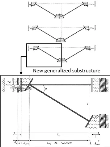
In particular, a fully analytical model has been de-veloped to predict the response of a steel or compo-site frame during Phase 3 (Huvelle et al, 2013, Hu-velle et al, 2015, Demonceau et al, 2017). The proposed analytical model is founded on the defini-tion of a substructure able to reflect the behaviour of the whole frame (Figure 2) and allows easily predict-ing the response of a 2D frame further to a column loss using the following assumptions:
a progressive (static) column loss is assumed;
the hinges can develop in the beam cross-sections or in the beam-to-column joints;
all columns are made of an unique cross-section type; and it is the same for the beams;
column bases are assumed to be perfectly fixed;
only the loss of internal columns (i.e. columns which are not at the corners) is considered;
no yielding develops in the indirectly affected part (i.e. its behaviour is assumed to be infinitely elastic).
The analytical model developed to predict the re-sponse of the so-defined substructure is detailed in (Huvelle et al, 2015). In this model, the behaviour of the yielded zones at the extremities of the beams subjected to combined bending moments and axial loads is reflected through a multi-layer spring model; this model allows reflecting the behaviour of this yielded zone if plasticity is developing in the beam or in the beam-to-column joints (if no group effects are developing between the bolt rows in case of bolt-ed connections and if no stress interactions are con-sidered at the level of the components).
The validity of the analytical model has been checked by comparing the predictions resulting from
its application to numerical results and experimental results (Demonceau & Jaspart, 2010). Through these comparisons, it has been demonstrated that the pro-posed analytical model is able to predict accurately the response of a steel or a steel-concrete composite frame during Phase 3.
Figure 2. Substructure model (Huvelle et al, 2015)
As previously mentioned, the proposed model is presently limited to specific joint configurations for which the behaviour of the joints is not affected by group effects and/or by stress interactions at the level of the components. However, these phenomena can have a significant influence on the resistance of joints subjected to M-N and so, more globally, on the response of the frames further to a column loss.
A further improvement should consist in substi-tuting to the multi-layer spring model illustrated in Figure 2 a more refined one able to (i) catch the group effects, (ii) take into account of the stress in-teractions at the level of the components and (iii) cover the successive loading conditions during the column loss (pure bending, bending and axial forc-es…). Such a spring model is under development at Liège University. Very promising results have al-ready been obtained; they should be published in a near future.
These works on joints are in the continuity of past investigations led in Liège since two decades. In par-ticular, the component method which is nowadays recommended in the Eurocodes to characterise the structural properties of joints in bending has been extended to predict the M-N resistance curve of steel and composite joints. Indeed, the component method
was first adapted in (Cerfontaine, 2003) to predict the behaviour of steel joints subjected to M-N and then, was adapted in (Demonceau, 2008, Jaspart, 2008) to predict the behaviour of composite joints subjected to M-N. Finally, the proposed model was also adapted to predict the behaviour of joints sub-jected to M-N at elevated temperatures (Demonceau, 2013, Haremza, 2016), loading situation which may occur, for instance, when the column loss is associ-ated to a localised fire. The validity of these devel-opments has been checked through comparisons to experimental results and the very good accuracy of the proposed model is clearly demonstrated in the previously mentioned references.
3 BEHAVIOUR OF 3D STRUCTURES
Based on the knowledge gain from the studies on 2D structures, investigations on 3D steel and steel-concrete composite structures have been conducted to investigate the possibility of extending the analyt-ical 2D model presented in the previous section. In a first step, parametrical studies on braced and unbraced steel structures made of steel members (without accounting for any contribution from the slab) have been conducted (Kulik, 2014, Ghimire, 2015). Though this work, it has been demonstrated that (i) the behaviour of 3D structures is similar to the one observed for 2D structures and (ii) the be-haviour of the 3D structures can be obtained by summing the contribution from the two 2D frames intersecting at the level of the lost column as illus-trated in (Figure 3).
Plane view of the 3D frame
Figure 3. Illustration of the response of a 3D braced structure further to a column loss (Ghimire, 2016)
Accordingly, through this observation, it can also be concluded that the analytical model presented in the previous section can be easily used to predict the re-sponse of a 3D structure made of steel (or steel-concrete) columns and of steel-concrete composite beams (through the concept of effective width for the concrete slab, as a simplified way to account for the latter).
However this way of accounting for the presence of the concrete slab in a composite 3D structure is seen to be conservative and that is why further ex-perimental (University of Stuttgart, 2016) and nu-merically (Mollica, 2015) studies on this specific as-pect have been performed.
Through these investigations, it has been possible (i) to demonstrate the ability of different numerical tools to simulate the behaviour of composite 3D structures in case of column loss scenario and (ii) to characterise the behaviour of composite floors (con-crete or composite slabs connected to the upper flanges of a steel grid) through parametrical cal studies performed with the so-validated numeri-cal tools. In particular, it has been demonstrated that:
The behavior of the slab is mainly governing the behavior of the composite slab in case of column loss scenario as membrane forces are developing in the slab as soon as small displacement are ap-pearing while the level of deformation reached af-ter the column loss is not sufficient to activate membrane forces in the composite beams;
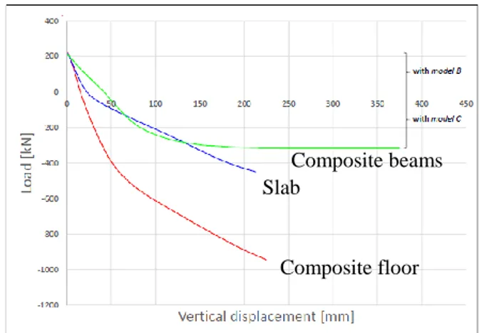
The global response a composite floor can be ob-tained by summing the contribution from the slab analyzed in isolation and the contribution from the composite beams analyzed in isolation as il-lustrated in Figure 4 where it can be observed that the curve reflecting the response of the composite floor can be obtained by summing the curve re-flecting the behavior of the slab simulated alone, i.e. without taking into consideration the steel beams connected to the slab though their upper flange and the curve reflecting the behavior of the composite beams simulated by only considering the part of the slab directly above the upper flange and collaborating with the steel profile (effective width).
So it appears that the behaviour of a composite floor can be analytically predicted as soon as analyti-cal models are available to predict the behaviour of the composite beams and of the slab in isolation.
For the composite beams, the previously intro-duced analytical model can be used. For the slab, it is recommended in (University of Stuttgart, 2016) to use the Bailey’s model (Bailey, 2002). In (University of Stuttgart, 2016), first research works have been conducted to demonstrate the ability of the Bailey’s model to predict the behaviour of a slab in case of column loss scenario with promising results. Further investigations are still required (i) to confirm these first results and (ii) to demonstrate that the sum of
the previously mentioned analytically predicted re-sponses provides an accurate prediction of the global behaviour of composite floors. At the University of Liège, it is intended to perform such further investi-gations.
Figure 4. Numerical prediction of the behaviour of a composite floor (Mollica, 2015)
4 DYNAMIC EFFECTS
The dynamic response of building frames further to a column loss has been investigated at the University of Liege in the last few years (Colomer, 2017, Comeliau, 2010, Comeliau, 2012).
To understand the behaviour of such frames, a basic substructure was first extracted and deeply studied for sake of simplicity. Indeed, frames losing a column proved to show many similarities in behav-iour with the above-considered simple substructure (Demonceau, 2008). This one, illustrated in Figure 5, is a double-beam system with a horizontal spring placed at one of the extremities of the beam and re-flecting the lateral restraint provided by the rest of the structure from which the studied beam is extract-ed (i.e. by the indirectly affectextract-ed part – Figure 1). The load P simulates the column loss (statically or dynamically applied).
Figure 5. Investigated double-beam substructure (Demonceau, 2017)
As far as dynamic loadings are concerned, the ap-plied force Pdyn(t) is considered to linearly increase
during a rise time tr and then to remain constant at a
maximum value equal to P (Figure 6). If values of P higher than Ppl are considered (Ppl being the value of
the static force causing the formation of the beam plastic mechanism), two main types of response have been observed through parametrical numerical studies, depending on the loading conditions defined
Composite floor Slab
by P and tr. These two types of response can be
ex-plained through comparisons between the dynamic curve ud(t) expressing the time evolution of the
dis-placement induced by the application of Pdyn(t) and
the static curve us(t) providing at each particular time
t* the static displacement ustat(P*) associated to the
value of the force P*=Pdyn(t*) (Figure 7 and Figure
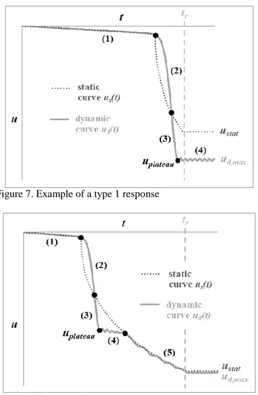
8). For type 1 response (Figure 7), it can be seen that the maximum dynamic displacement which is reached is higher than the static displacement which would have been observed while for type 2 response (Figure 8), it can be observed that the maximum fi-nal displacement obtained through a dynamic afi-naly- analy-sis is similar than the one which would have been reached through a quasi-static removal of the col-umn. The shape of the curves reported in Figure 7 and Figure 8 are described and justified in details in (Demonceau, 2017).
Figure 6. Dynamic loading applied to the substructure (Demon-ceau, 2017)
Figure 7. Example of a type 1 response
Figure 8. Example of a type 2 response
Based on these observation, a simplified model was developed for the prediction of the substructure dynamic response (Comeliau, 2012). This model is based on energy considerations and consists in writ-ing that the work done by the external load is equal to the sum of the kinetic energy and the deformation energy. For this simple system, the deformation en-ergy could be expressed as a function of the vertical displacement at mid-length, considering the work re-lated to the plastic hinges rotation and the lateral spring elongation. The plastic interaction between the bending moment and the tension force in the plastic hinges has been taken into account as well as the elongation of the beams. With the developed an-alytical model, it is possible to predict the displace-ment vs. time response of the simplified model knowing its quasi-static response (which can be pre-dicted using the analytical model previously present-ed in this paper). This analytical model has been val-idated through comparison between numerical and analytical predictions. Illustrations of such compari-sons for type 1 and type 2 responses are given in Figure 9.
Figure 9. Validation of the substructure dynamic model (Demonceau, 2017)
Then, in (Demonceau, 2017), it is demonstrated how the developed model can be easily extended to the prediction of the response of a full frame sub-jected to the dynamic loss of a column. In particular, it is shown that the displacement vs. time response of the frame is predicted with a very good accuracy when compared to numerical results.
Accordingly, a full analytical model able to pre-dict the dynamic response of structures further to a column loss is available; knowing the geometrical and mechanical properties of the structural elements and the time tr associated to the column loss (see
Figure 6), it is possible to predict the maximum dy-namic displacement ud,max reached during the
col-umn loss. Knowing the maximum dynamic dis-placement, it is possible to assess the required ductility and resistance for the different structural el-ements.
Indeed, many finite element analyses (University of Stuttgart, 2016) demonstrated that the distribution of internal forces in a frame corresponding to a given value of the displacement u is the same no matter if this displacement is reached statically or dynamical-ly (provided this displacement is reached for the first time - the unloadings and reloadings associated to the system oscillations are not considered).
Consequently, if the static response is known, the dynamic maximum displacement can be determined using the proposed model; and then the correspond-ing distribution of internal forces can be deduced from the static response. If the structure is able to statically reach the displacement ud,max, then the
dy-namic robustness is ensured.
The main difficulty in the proposed procedure is to be able to predict the time tr associated to the
colun loss, this value strongly depending of the na-ture of the exceptional event associated to the col-umn loss. In the framework of the Robustimpact pro-ject (University of Stuttgart, 2016), the University of Liège and the RWTH of Aachen combined their ef-forts to solve it for the specific scenario “impact of a vehicle on a column” (Colomer, 2017). In particular, RWTH developed a model able to predict the local response of a column in a frame when subjected to an impact, taking into account the effect of the re-straint and the inertia of the surrounding structure. Merging this model with the “Liège” model previ-ously mentioned, it was possible to predict the re-sponse of a frame subjected to an impact (for differ-ent level of energy) through a fully analytical procedure (see Figure 10 - Colomer, 2017).
Figure 10. Dynamic response of a structure predicted with the proposed analytical model under different column damage sce-narios (Colomer, 2017)
Last but not least, it has to be mentioned that in all the presented dynamic models, the possible strain rate effects have not yet been implemented. These effects are still under investigations at the University of Liège, in particular when these effects are devel-oping at the level of the beam-to-column joints; this point is addressed in a second paper presented within the present conference.
5 CONCLUSIONS
Within the present paper, recent developments per-formed at the University of Liège in the field of ro-bustness and, more precisely, for the specific scenar-io “loss of a column in a steel or steel-concrete composite building” have been briefly presented. The objective of the present paper was to highlight the followed global strategy, passing from the quasi-static behaviour of 2D frames to the dynamic behav-iour of 3D structures, and the main outcomes of the conducted researches, referring to recent publica-tions for the details.
In particular, it is demonstrated how analytical models have been developed with the objective of easily predicting the behaviour of structures for the considered scenario, the main interest of the analyti-cal models being that all the structural properties and parameters affecting the response of the structures are identified and mastered. Having identified these structural properties, it will be possible in a next step to derive design requirements useful for practitioners and able to ensure an appropriate behaviour of a structure in case of a column loss scenario. These ones could then be possibly implemented one day in the Eurocodes. This constitutes the main perspective of the presented developments.
6 ACKNOWLEDGEMENT
Part of the presented work was carried out with financial grants from the Research Fund for Coal and Steel of the European Community, within Ro-bustness project Grant N° RFS-CR-04046, Robust-fire project Grant N° RFSR-CT-2008-00036 and Robustimpact project Grant N° RFSR-CT-2012-00029.
7 REFERENCES
Bailey C. 2002. Structural fire design of unprotected steel beams supporting composite floor slabs. Summary of what
was presented at the “International Conference on Steel Construction-CICOM”. Sao Paulo, Brazil.
Cerfontaine F. 2003. Etude de l'interaction entre moment de flexion et effort normal dans les assemblages boulonnés. PhD Thesis. University of Liège.
Colomer Segura C., Hamra L., D’Antimo M., Demonceau J.-F. & Feldmann M. 2017. Determination of loading scenarios on buildings due to column damage. Structures, Vol. 12, Nov. 2017, pp. 1-12.
Comeliau L., Demonceau J.-F. & Jaspart J.-P. 2010. Robust-ness of steel and composite buildings under impact loading. Proceeding of SDSS’Rio 2010: International Colloquium Stability and Ductility of Steel Structures, pp. 393-400. Comeliau L., Rossi B. and Demonceau J.-F. 2012. Robustness
of steel and composite buildings suffering the dynamic loss of a column. Structural Engineering International: journal
of the international association for bridge and structural engineering, Vol. 22/3, pp. 323-329.
Demonceau J.-F. 2008. Steel and composite building frames: sway response under conventional loading and development of membrane effects in beams further to an exceptional ac-tion. PhD thesis. University of Liege (freely downloadable at: http://hdl.handle.net/2268/2740)
Demonceau J.-F., Comeliau L., Hoang V. L. & Jaspart J.-P. 2017. How can a steel structure survive to impact loading?
The Open Civil Engineering Journal, Vol. 12, pp. 434-452.
Demonceau J.-F., Comeliau L. & Jaspart J.-P. 2011. Robust-ness of building structures – recent developments and adopted strategy, Steel Construction – Design and
Re-search, Ed. Ernst & Sohn (Wiley Company), Vol. 4/3,
Au-gust 2011, pp. 166-170.
Demonceau J.-F. & Jaspart J.-P. 2010. Experimental test simu-lation a column loss in a composite frame. Advanced Steel
Construction, Vol. 6, pp. 891-913.
Demonceau J.-F., Haremza C., Jaspart J.-P., Santiago A. & Si-moeas da Silva L. 2013. Composite joints under M-)N at elevated temperaturas – Experimental investigations and analytical model. Proceeding of the Composite
Construc-tion VII conference. Palm Cover, Australia.
Ghimire A. 2016. Robustness of 3D steel structures further to a column loss: identification of structural requirements through parametrical studies. Master thesis presented at the
University of Liege, 2015-2016.
Haremza C., Santiago A., Demonceau J.-F., Jaspart J.-P., Si-moes da Silva L. 2016. Composite joints under M-N at
ele-vated temperatures. Journal of Constructional Steel
Re-search, Vol. 124, Sept. 2016, pp. 173-186.
Huvelle C., Hoang V. L., Jaspart J.-P. & Demonceau J.-F. 2015. Complete analytical procedure to assess the response of a frame submitted to a column loss, Engineering
Struc-tures, Vol. 86, pp. 33-42.
Huvelle C., Jaspart J.-P. & Demonceau J.-F. 2013. Robustness of steel building structures following a column loss.
Pro-ceedings of IABSE Workshop “Safety, Failures and Ro-bustness of Large Structures”, Helsinki.
Jaspart J.-P. & Demonceau J.-F. 2008. Composite joints in ro-bust building frames. Composite Construction in Steel and
Concrete VI, proceeding of the conference, Colorado, 2008,
pp. 442-454.
Kulik S. 2014. Robustness of steel structures: consideration of couplings in a 3D structure. Master thesis presented at the
University of Liege, 2013-2014.
Mollica A. 2015. Development of membrane forces in a steel-concrete composite floor during the loss of a column. Mas-ter thesis presented at the University of Liège, 2014-2015 University of Stuttgart, University of Liège, University of
Aa-chen RWTH, INSA Rennes & ArcelorMittal. 2016. Robust impact design of steel and composite building structures (Robustimpact). Final Report. EU Grant Agreement Num-ber RFSR-CT-2012-00029.