SENSITIVITY OF STRUCTURES TO FIRE DECAY PHASES
Quantitative Comparison of Structural Components made of Different Materials Thomas Gernay
The National Fund for Scientific Research, University of Liege, Structural Engineering Department, Liege, Belgium Abstract
This work presents an analysis of the behaviour of different structural members under natural fires, with the aim to characterize their sensitivity to the fire decay phase. Thermo-mechanical numerical simulations based on the non-linear finite element method are conducted using the parametric fire model of Eurocode to represent the natural fires. Results show that, for all the studied members (column, beam) and materials (reinforced concrete, steel, timber), structural failure during or after the cooling phase of a fire is a possible event. The major factors that promote delayed structural failure are the thermal inertia and the constituting material of the member. An indicator is proposed to quantify the propensity to delayed failure for structural members under natural fire. This work enhances the understanding of the structural behaviour under natural fires and has implications for the safety of the fire brigades and people proceeding to a building inspection after a fire.
Keywords: Natural Fire, Structures, Performance-Based Design, Decay Phases
1 INTRODUCTION
In a performance-based approach, the fire models used in the analysis aim to capture a realistic representation of the fires that may occur in a building. As a consequence, the fire models include the successive fire development stages until burnout, rather than consisting in continuously increasing time-temperature curves (such as the standard ISO fire). However, the effects of these realistic fires on the structural response, and specifically the effects of the decay phases, are not yet fully understood. Recent events of building collapse during or after the decay phase of fires have highlighted the paramount importance of filling this lack of knowledge.
Research on structural behaviour after the time of maximum temperature are scarce and focus mainly on residual load-bearing capacity. However, more attention should be brought to the structural behaviour during and right after the cooling phase of the fire, because the vulnerability of a structure is important in these phases during which the elevated temperature has not dissipated yet. Besides, structural failures arising during these decay phases pose a serious threat to fire fighters. Therefore, this research focuses on the analysis of structural response in the decay phases of a natural fire. To allow for comparative analyses and quantification of the response, a novel indicator (i.e., a measure of performance) is proposed. The paper describes the method to derive the indicator and apply it to assess the performance of different structural members under natural fires.
2 NUMERICAL ANALYSIS OF STRUCTURAL MEMBERS UNDER NATURAL FIRE 2.1 Geometry and Section Properties
The study consider a reinforced concrete (RC) column, a protected steel column and a timber beam. (1) A RC column of 4 m length is exposed to natural fire on its four sides. The column is simply supported at both ends with no restrain in thermal expansion. A sinusoidal imperfection with amplitude of L/300 is introduced along the column length. It is submitted to a vertical load applied at the centre of the top section. The column has a square cross section of 450 mm side, with 12 rebars of 16 mm diameter and a concrete cover of 30 mm. The concrete compressive strength and the steel reinforcement yield strength at ambient temperature are equal to 30 MPa and 500 MPa, respectively. The maximum compressive load at the beginning of the fire (i.e. capacity at ambient
temperature) is 6338 kN. The column has a fire resistance of 120 minutes when loaded at 50% of its maximum compressive load at the beginning of the fire (i.e., 50% load ratio (LR)).
(2) A HEB 400 steel column in S355 is exposed to natural fire on its four sides. The column is 4 m length, it is simply supported at both ends and it has a sinusoidal imperfection with amplitude of L/300. Flexural buckling about the weak axis of the section was prevented. It is submitted to a vertical load applied at the centre of the top section. The maximum compressive load at the beginning of the fire is 6256 kN. The column is analysed with two different thermal protections. In the first case (P1), the applied thermal protection provides a fire resistance of 60 minutes under 50% applied load ratio. In the second case (P2), it provides a fire resistance of 120 minutes under 50% applied LR (i.e., similar to the fire resistance of the RC column). This latter fire resistance is achieved using a thickness of 20 mm of sprayed fire-resistive material (SFRM) with the following thermal properties: thermal conductivity 0.12 W/mK, specific heat 1200 J/kgK, specific mass of the dry material 350 kg/m³, water content 20 kg/m³.
(3) A softwood timber beam, simply supported with 4 m span, is exposed to natural fire on 3 sides. The beam cross-section is rectangular with a height of 0.60 m and a width of 0.30 m. The applied load is uniformly distributed on the beam and maintained constant during the fire. The Young’s modulus and characteristic bending strength were taken as 11 GPa and 24 MPa at ambient temperature, respectively.
2.2 Model Assumptions
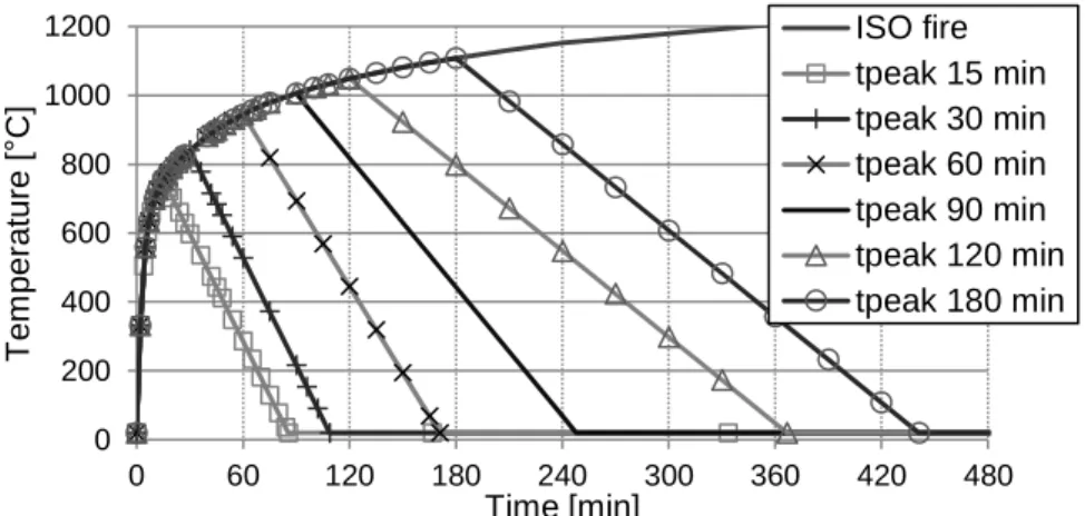
The adopted model for the natural fires is the parametric fire model from Eurocode (EC1, 2002). It is chosen to set the value of the factor Γ at 1.0 in the model, which makes the heating phase of the time-temperature curve of this natural fire model approximates the standard ISO curve. Hence, the only varying parameter in the natural fire model is the duration of the heating phase tmax. Figure 1 shows the time-temperature curves for different values of tmax.
0 200 400 600 800 1000 1200 0 60 120 180 240 300 360 420 480 T e m p e ra tu re [ ° C ] Time [min] ISO fire tpeak 15 min tpeak 30 min tpeak 60 min tpeak 90 min tpeak 120 min tpeak 180 min
Fig. 1 Eurocode Parametric Fire Model for Natural Fire.
Fig. 2 Sections of the RC column (left), the HEB400 steel column (centre) and the timber beam (right). For the RC column, half of the section is modelled, taking advantage of symmetry.
The study is conducted using non-linear finite element (FE) analysis. The software SAFIR (Franssen, 2005) is used for the analysis of the heat transfer processes and the thermo-mechanical behaviour of the member. First, a two-dimensional thermal FE analysis is conducted for the heated member using a fiber discretization of the cross-section, see Figure 2. Then, a structural analysis is performed using three-noded, two-dimensional beam elements. The time-temperature evolution in each fiber results from the previously conducted thermal analysis. The structural analysis takes into account geometrical and material non-linearity, including large deflections.
The thermal properties of steel and concrete in the heating phase are taken from Eurocode (EC4, 2005). Where concrete is used, siliceous concrete is chosen, with a density of 2400 kg/m³ and a water content of 48 kg/m³. The emissivity is taken as 0.7 and the coefficient of convection between concrete and the air is 35 W/m²K. The emissivity of SFRM is taken as 0.8.
The mechanical properties of steel are considered as reversible, which means that stiffness and strength are recovered to full initial values during cooling. The mechanical behaviour of steel follows the model of Eurocode (EC3, 2005). For concrete, a residual thermal expansion or shrinkage is considered when the concrete is back to ambient temperature, the value of which is taken as a function of the maximum temperature according to experimental tests published in the literature (Franssen, 1993). As prescribed in EC4, an additional loss of 10% of the concrete compressive strength is considered during cooling, with respect to the value at maximum reached temperature. This additional reduction during cooling is supported by many experimental studies (Yi-Hai et al., 2011). The Explicit Transient Creep Eurocode model is adopted to take into account the transient creep strain irreversibility during cooling (Gernay, 2012).
For wood, the numerical calculations are made in accordance with the advanced calculation method of Annex B of Eurocode (EC5, 2004), based on the theory of heat transfer by conduction. The emissivity and convection coefficient are taken equal to 0.8 and 35 kW/m², respectively. The conductivity, specific heat and density vary with temperature following the EC5 relationships. Moisture content and density at ambient temperature are assumed as 12% and 450 kg/m³, respectively. The temperature dependent relationships of Eurocode 5 were adopted for the strength and stiffness. Accordingly, the strength and stiffness of softwood start to decrease as soon as the temperature exceeds 20°C and they reduce to zero at 300°C. More details about the modelling assumptions for wood under natural fire exposure are given in (Gernay et al., 2015).
2.3 Thermo-Mechanical Numerical Simulations
The objective of the simulations is to assess the response of the structural member during the course of the natural fire. For a given structural member, numerical simulations are run under different natural fire exposures (see Figure 1).
When a member is exposed to a natural fire, its load bearing capacity decreases during the heating phase of the fire, but it also decreases after the maximum gas temperature is attained, finally reaching a minimum value (which may in some cases occur long after the temperature in the atmosphere is back to ambient). Then, the load bearing capacity may remain constant or eventually recover partially or completely when the temperatures in the structure are back to ambient. This delayed decrease in load bearing capacity may be caused by the combination of various phenomena among which the delayed temperature increase in the sections due to thermal inertia and the non-recovery or additional loss of material mechanical properties during cooling (Gernay et al., 2013). For instance, Figure 3 shows the results of three numerical simulations conducted on the RC column exposed to a natural fire with a duration of heating phase of 60 minutes. What is plotted is the evolution of vertical deflection at the top of the column with time. The applied loads on the column (held constant during the fire) correspond respectively to load ratios (LR) of 55%, 60% and 65%. As can be seen, the LR of 65% leads to structural failure after 78 minutes. Note that this means that the failure arises during the cooling phase (since the natural fire has a 60-minutes heating phase). On the other hand, when subjected to a LR of 60%, the column fails after 241 minutes. This is a significant delay compared to the end of the fire. Finally, the column does not fail under a LR of 55% (note that the simulation was run for 16 hours to check that the column does not fail, but the scale of the x-axis has been limited for the sake of clarity). It results that the load
bearing capacity remains constantly larger than 55% of the capacity at ambient temperature when this column is exposed to this particular natural fire.
Similar analyses are conducted for the other members (steel column, timber beam) and for varying natural fire curves and applied load ratios. The results are analysed in the next Section, after introducing a suitable indicator.
3 DURATION OF THE HEATING PHASE (DHP) INDICATOR 3.1 Theoretical Definition of the Indicator
The key idea behind the proposed indicator is to relate the applied load ratio on a member with a duration characteristic of a natural fire, just as the fire resistance rating (R) relates the applied load ratio with the duration of exposure to a standard fire until failure. In the case of a natural fire, the characteristic duration is chosen as the duration of the heating phase (DHP), which is equal to tmax. For a given member, subjected to a given natural fire, one can assess the evolution of the load bearing capacity during the course of the natural fire. To do so, several simulations are successively run until failure for varying levels of applied load (maintained constant during the fire). At time of failure, the applied load is equal to the load bearing capacity. For instance, for the RC column shown in Figure 3, the load bearing capacity ratio is 60% after 241 minutes. The time evolution of the load bearing capacity is thus obtained point-by-point as the result of several simulations run until failure.
Figure 4 shows, for the RC column, the evolution of the load bearing capacity under different fire exposures: natural fires with DHP (≡tmax) of 30 min, 60 min and 120 min, and the standardized ISO fire. When subjected to the ISO fire, the load bearing capacity decreases continuously as a result of continuously increasing gas temperatures. However, in case of natural fire exposure, the load bearing capacity reaches a minimum value, after which it will remain constant or recover.
It is interesting to relate this minimum value of the load bearing capacity with the DHP of the natural fire. For instance, for the RC column, the load bearing capacity reaches a minimum of 72% when subjected to a natural fire with a DHP of 30 minutes. This means that, if the applied LR is lower than 72% and the member is subjected to this fire, it will survive the total duration of the fire, until complete burnout. Inversely, if the applied LR is higher or equal than 72%, the RC column will fail due to the fire. On the other hand, if the applied LR is 72%, one can also say that the column will fail if it is exposed to a natural fire with a DHP of a least 30 minutes. Hence, the DHP indicator is based on the minimum duration of a fire heating phase that affects the structural component to such an extent that the latter is expected to fail even if the fire stops thereafter.
Load Ratio 55% Load Ratio 60% LR 65% Fire 0 200 400 600 800 1000 1200 -30 -25 -20 -15 -10 -5 0 0 60 120 180 240 300 360 420 480 T e m p e ra tu re [ ° C ] T o p V e rt ic a l D e fl e c ti o n [ m m ] Time [min] II Cooling I Heating III
Gas Temperature back at ambient
Fig. 3 Time evolution of top vertical displacement for a RC column exposed to a 60-minutes heating phase natural fire, for different levels of applied compressive load.
LR=60% DHP=60 min LR=72% DHP= 30 min LR=39% DHP=120 min 0% 10% 20% 30% 40% 50% 60% 70% 80% 90% 100% 0 60 120 180 240 300 L o a d R a ti o [ -] Time [min]
Load bearing capacity evolution under different fires tmax=30 min tmax=60 min tmax=120 min ISO fire DHP curve
ISO fire ≡ 'R' curve
Fig. 4 Evolution of the load bearing capacity of a RC column under different fire exposures. The RC column loaded at 72% of its maximal capacity at ambient temperature has a DHP of 30 min and a R of 57 min.
As shown in Figure 4, the DHP indicator is thus derived from the load bearing capacity curves, by relating the minimum value of the capacity to the duration of the heating phase of the natural fire (which is as defined in Figure 1). By definition, the DHP of a member under a given applied LR represents the minimum exposure time to standard ISO fire (followed by cooling phase in accordance with the Eurocode parametric fire model) that will eventually result in the failure of the structural component. It is always smaller than or equal to the Fire Resistance R.
3.2 Analysis of the Results Using the Indicator
Table 1 summarizes the results of the numerical simulations performed in Section 2. For the 4 members analysed in this paper, the table gives the DHP and the Fire Resistance R under different applied load ratios. For instance, for the RC column under 40% applied LR, the DHP is equal to 116 min, whereas the fire resistance is 164 min (which is also visible in Figure 4).
The results of Table 1 are plotted in Figure 5. This leads to the following main observations:
- The DHP is always lower than the Fire Resistance, which reveals the possibility of delayed failure for all the studied members.
- The difference between the DHP and R is higher for certain members (e.g. Steel column P2) than for others (e.g. Steel column P1). It is also higher for the timber beam. This reveals the effects of different mechanisms influencing delayed failures, such as the thermal inertia due to steel thermal insulation (P2 = more insulation than P1) and the delayed charring process in a timber member. - It is frequent for two structural members to have the same R (under given load ratios) but different DHP. The member with the largest DHP has the advantage of performing better under natural fire. The DHP allows to assess which structural member is more prone to delayed failure. When considering natural fires, it is necessary to use the DHP, in conjunction with the Fire Resistance R, to get a comprehensive evaluation of the performance of a structural member.
Table 1 Indicators R and DHP for the structural members under different load ratios. Time in min RC column Steel Column (P1) Steel Column (P2) Timber Beam
Load Ratio DHP R DHP R DHP R DHP R
60% 60 88 35 54 72 108 15 51
50% 89 120 43 61 84 120 26 71
40% 116 164 50 69 97 135 39 92
0 60 120 180 0 60 120 180 240 D H P [ m in ] R [min] RC column Steel Column (P1) Steel Column (P2) Timber Beam
Fig. 5 The distance to the bisector in the R-DHP space reflects the propensity to delayed failure.
4 CONCLUSIONS
Delayed structural failures, arising during or after the cooling phase of a fire, may occur with all types of structural members and constituting materials. These result from different mechanisms such as the effects of thermal inertia or the additional loss of mechanical properties during cooling. This possibility of delayed failures must be correctly assessed when considering more realistic fire scenarios, notably for a better assessment of safety during fire brigades intervention.
This research proposes a method to derive an indicator, the DHP, which constitutes a pragmatic measure that can be used to compare different structural members in terms of their propensity to delayed failure. At the practical level, the couple of indicators (DHP, R) allows dividing the post-flashover time domain in three parts for a structure in fire, at least if the temperature development in the post-flashover phase is in the order of magnitude of the standardized fire. As long as the heating time passed after flashover is shorter than the DHP, the structure is theoretically safe; as soon as it exceeds the DHP, the structure has been affected to such an extent that it is expected to fail even if the fire stops thereafter; and when the post-flashover time of heating exceeds R the structure is theoretically collapsed. This information may be valuable for firefighters, who could use it when they arrive on site for mitigating the risk during their intervention.
REFERENCES
EC1. 2002. EN 1991-1-2. Eurocode 1: Actions on Structures - Part 1-2: General actions – Actions on
structures exposed to fire. Brussels: CEN.
EC3. 2005. EN 1993-1-2. Eurocode 3 - Design of steel structures - Part 1-2: General rules - Structural fire
design. Brussels: CEN.
EC4. 2005. EN 1994-1-2. Eurocode 4 – Design of composite steel and concrete structures. Part 1–2:
General rules – Structural fire design. Brussels: CEN.
EC5. 2004. EN 1995-1-2. Eurocode 5 - Design of timber structures - Part 1-2: General - Structural fire
design. Brussels: CEN.
Franssen JM. 1993. Thermal elongation of concrete during heating up to 700°C and cooling. University of Liege. http://hdl.handle.net/2268/531.
Franssen JM. 2005. SAFIR: A thermal/structural program for modeling structures under fire. Engineering
Journal – American Institute of Steel Construction, 42(3), p. 143-158.
Gernay T. 2012. Effect of Transient Creep Strain Model on the Behavior of Concrete Columns Subjected to
Heating and Cooling. Fire Technology, 48(2), p. 313-329.
Gernay T, Franssen JM. 2012. A formulation of the Eurocode 2 concrete model at elevated temperature that
includes an explicit term for transient creep, Fire Safety Journal, 51, p. 1-9.
Gernay T, Dimia MS. 2013. Structural behaviour of concrete columns under natural fires. Engineering Computations, 30(6), p. 854-872.
Gernay T, Franssen JM. 2015. A performance indicator for structures under natural fire, Engineering
Structures, 100, p. 94-103.
Yi-Hai L, Franssen JM. 2011. Test results and model for the residual compressive strength of concrete after