Application of C.A.P.E. techniques to the
revamping of existing electrical power plants :
an example of interdisciplinary collaboration.
Georges Heyen a, Bruno Vrielynck b, Boris Kalitventzeff a,b
a L.A.S.S.C., Université de Liège, Sart-Tilman Bâtiment B6, B-4000 Liège (Belgium) email : [email protected]
b Belsim s.a., 1 allée des Noisetiers, B-4031 Angleur - Liège (Belgium)
Abstract : Coupling of a partial oxidation reactor with a gas turbine is proposed to increase the capacity and efficiency of thermal power plants. The exhaust of the partial oxidation gas turbine is a preheated fuel that can be burned with little modification in the existing steam generator. The feasibility study requires the development of a reliable model for an existing 250 MW power plant. Data reconciliation is found valuable for obtaining precise mass and energy balances and for screening out unreliable measurements. The identification of model parameters from reconciled values is then straightforward.
The same validation software is later applied to rating simulation of the modified plant, by merging the partial oxidation gas turbine in the model.
Keywords : Advanced power cycles, Energy efficiency, Cogeneration, Data reconciliation, State identification, Plant design.
INTRODUCTION
In view of the constant growth of electricity usage and public pressure to reduce the dependence on nuclear power plants in the energy supply, solutions are sought to increase the capacity of power plants burning fossil fuels. Highly efficient cycles are available: gas turbines combined with waste heat
boilers and steam cycles are able to achieve efficiencies in the 50-55% range. However building new plants requires a large amount of capital.
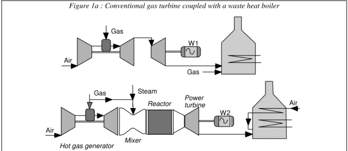
Alternative proposals are based on upgrading existing plants : a number of them only achieve to transform 40% of the fuel lower heating value into electricity. Some of those plants are still in good condition of maintenance, and a longer service life Figure 1a : Conventional gas turbine coupled with a waste heat boiler
Air Gas Gas W1 Air Gas Steam
Hot gas generator Mixer
Reactor Powerturbine Air W2
could be expected from available equipment. Depending on age, size and configuration of the existing plant, a number of rehabilitation concepts can be compared.
The simplest way to increase the power of an existing plant is to install additional generators and prime movers in parallel to the existing equipment. Installing a gas turbine coupled with a generator is a relatively low investment.: aeroderivative turbines are available in a range of power, and allow flexible operation (short start-up time). However their efficiency is low (in the order of 30%), since most of the fuel energy is lost in the stack gas.
The exhaust of the gas turbine still contains a large amount of oxygen and its temperature is relatively high : it can replace the preheated air flow in the combustion chamber of the boiler. Combining a steam and a gas cycle is known to improve considerably the efficiency of work production, and many combined cycle plants have recently been put in operation. However the conversion of existing large steam power plants with reheat to combined cycle power plants is a rather new concept, and this change implies large modifications of the steam generator structure (Heyen et al., 1996a).
An alternative solution is the use of a partial oxidation gas turbine. As shown in figure 1B, a hot mixture of compressed air, steam and natural gas is fed to a catalytic partial oxidation reactor. The compressed air can be supplied by an existing gas turbine whose last expander stage has been removed, or by an independent compressor followed by a heat exchanger. Such an alternative is attractive, since lower investment and shorter shut down time are needed (OXIPAR, 1997).
The performance of present gas turbines is limited by materials constraints. A thermodynamic analysis shows that the efficiency of the reference Joule cycle increases with the compression ratio (and thus with the inlet temperature in the combustion chamber). However the resistance of turbine blades limits the combustion temperature, even if the development of new alloys and progress in blade design (e.g. integral cooling with compressed air) allows to increase this limit continuously (from 900°C in the 60's, to 1300°C
in recent designs). When the machine efficiency is taken into account, the optimal turbine inlet temperature appears to be related to the cycle maximum pressure.
The most obvious way to limit the combustion temperature is to use a large excess of combustion air. Figure 2 shows how the reaction temperature varies with the air to fuel molar ratio (adiabatic equilibrium, no preheat, fuel = pure CH4, air=21%O2,79%N2). The
maximum temperature is obtained when fuel and air are mixed close to stoichiometric proportions. Temperature drops when air is brought in excess, due to dilution of the combustion products, as it is typically done in gas turbines. For instance, the combustion temperature can be brought down to 1250 K when the air to gas ratio is set to 27, as illustrated in figure 2. But the same temperature can be attained using sub-stoichiometric proportions (approximately 4.5). In these conditions, the combustion of methane is not complete. The oxidation product is a mixture of CO, CO2, H2, H2O,
N2 and unreacted CH4.
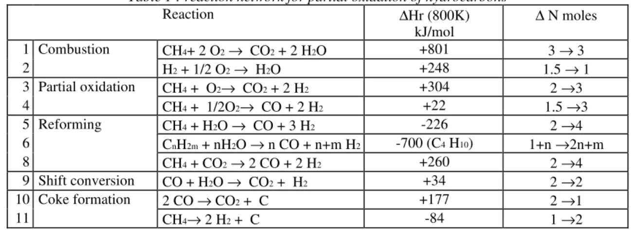
Table 1 reviews competing reactions occurring during partial oxidation. Partial oxidation reactions (3, 4) are exothermic, but the energy release is much lower than for total combustion (1, 2). Furthermore, steam reforming reactions (5, 6) are endothermic.
T(K) 0.0 500.0 1000.0 1500.0 2000.0 2500.0 0 5 10 15 20 25 30 air/NG CH4 + 0.5 O2 CO + 2 H2 CH4 + 2 O2 CO2 + 2 H2O
Figure 2 : adiabatic reaction temperature
Table 1 : reaction network for partial oxidation of hydrocarbons
Reaction ∆Hr (800K) kJ/mol ∆ N moles 1 Combustion CH4+ 2 O2→ CO2 + 2 H2O +801 3 → 3 2 H2 + 1/2 O2→ H2O +248 1.5 → 1 3 Partial oxidation CH4 + O2→ CO2 + 2 H2 +304 2 →3 4 CH4 + 1/2O2→ CO + 2 H2 +22 1.5 →3 5 Reforming CH4 + H2O → CO + 3 H2 -226 2 →4 6 CnH2m + nH2O → n CO + n+m H2 -700 (C4 H10) 1+n →2n+m 8 CH4 + CO2→ 2 CO + 2 H2 +260 2 →4 9 Shift conversion CO + H2O → CO2 + H2 +34 2 →2 10 Coke formation 2 CO → CO2 + C +177 2 →1 11 CH4→ 2 H2 + C -84 1 →2
Conversion reaction (9) is only slightly exothermic. CO2 reforming (8) is not significant at moderate
pressure in the absence of a specific catalyst. Coke formation (10, 11) is too be avoided in practice : this can be achieved by adding steam to the reactants.
Interestingly, the number of moles increases during partial oxidation and reforming reactions (3-8), as shown in the last column of table 1. This increases the work production of a partial oxidation gas turbine compared to a classical full combustion gas turbine, since the number of moles expanded in the power turbine is larger than the number of moles to be compressed. For the same air flow rate (and thus for the same compressor size), the work developed in a partial oxidation gas turbine will be larger than for a conventional machine.
Furthermore the exhaust of the partial oxidation gas turbine is a hot fuel, similar to coke oven gas or blast furnace gas, and it has to be further oxidized at low pressure to result in a feasible process. The partial oxidation gas turbine fully justifies its efficiency in connection with a furnace where heat released by the post combustion can be valorised for process heating.
A sensitivity analysis shows that the energy efficiency of partial oxidation gas turbine coupled with a furnace is higher than the combination of a furnace with a conventional GT when the furnace must deliver heat at high temperature (above 400°C). The partial oxidation technology relies partly on existing standard equipment : turbojets for air planes, whose parts can be reused or adapted to verify similarity conditions. It provides a significant increase of the power generation capacity, while improving the overall cycle efficiency. As an extra advantage, it has a favourable impact on emission of pollutants (NOx), since the combustion temperature remains moderate.
The partial oxidation gas turbine is presently under development in Belgium. After some theoretical analyses based on computer simulation models, experimental investigation has been initiated in 1996. A test bench has been installed to screen the operating conditions and test several industrially available catalysts. The influence of pressure, temperature, steam to carbon ratio, air to carbon ratio and residence time in the reactor have been studied.
In a second stage, a small scale test bench has been built. It is based on an aeroderivative gas turbine, with a nominal power of 80 kW. The gas generator of this machine has been uncoupled from the power turbine. Preheated steam and propane are added to the gas generator exhaust gas and fed to the catalytic bed. An expander and a nozzle are mounted downstream in parallel. Product gas is burned in a flare. This small scale unit has illustrated the workability of the concept, and has helped identify areas for further developments : fluid mixing, pressure drops, process control during start-up and shut down. A CFD model has been developed to redesign the mixing chamber, and a dynamic simulation model of the complete set up has been
tuned and will be used to support the design of the control system.
Based on the results of this preliminary study, two larger scale projects have been initiated :
- addition of a partial oxidation gas turbine to an existing steam generator operated on a chemical site (power generation in the 1-2 MW range); - revamp of an existing 250 MW electrical power
plant and comparison with similar project based on a conventional gas turbine.
The application of CAPE tools in the preliminary analysis of this second project will be further described.
! " #$% #&" ' ( % ' "& $ % " & " "& $ )' % # $ &$
& * + % ! , - % , ' "& $ .
' %&$ # $ /' % , % 0
$ - ' %&$, % 0 !" ( %&$ 1 & $ ! $ $ &- %&$ % /" #&$ & 2 ! $ &$ )# & #$ 1 &+ * ' $ - $ &# + & !! # #3 . 3 $ ' ' $ #3 #" ( $ & & $, %* / $ % # + $ &" % * & ' &%$ &" ) &$ 10 #& )' #$ ! #& $ # & $ # - * , $ ' % # &
$ %&$ ! &$ $%& ! %.
! % &" ( $ $ !, "" # - ' " ) $3 ! & &#$, &" $ &- #3 #" 0 & ! & * " $3 $, 3 & * #&%% , $ $ $ !3 $ ' $ $ &" ' $!&"" 0 & $ $ #$ ( &$
&% $ - $ $ + &% & $
' % # 0 ! % ( # $ - " , " * ' &%$ #, "&%"3 % " &* " .
The reference is a Rankine cycle with steam reheat and water preheating using extracted steam, and is illustrated in figure 3. Superheated steam is produced at 810 K, 180 bar. After first expansion, a part of it (approx. 20%) is extracted to preheat boiler feed water, and the rest is reheated to 805 K. After a second expansion to 5.5 bar, some more steam is extracted to heat the feed drum. A third extraction occurs after expansion to 0.8 bar. Condenser nominal pressure is 0.06 bar.
The model has been developed using the data reconciliation software BELSIM-VALI 3, in which specifications have been treated as pseudo
, % 4 - ' " ! & 5 #3 #" 0 % ! % # #& NG CW FUMES AIR 304 kg/s 97 C 17.5 kg./s Net power 344 MW Efficiency 42.4 % 2137 C 271 546 180 219 533 42.4 214 268 5.5 199 92 0.76 kg/s C bar 214 35 .056 214 73 2 271 123 2 271 211 182 343 C 271 358 181 219336 43.4 97 114 73 66 MW 322 kg./s 101 C 361 C 319 kg./s
measurements, and selected to match exactly the number of degrees of freedom of the model, thus resulting in a flowsheeting problem. Even if some simplifications have been introduced in the model (namely the number of extraction stages is usually larger), such a cycle is representative of currently operating plants.
The net power generated is 350 MW (detailed figures for each turbine stage are given in table 2), thus the calculated thermal efficiency is 42 %. This figure might look high, but in all the models used in this preliminary study, heat losses to the environment, mechanical and transformation losses have been ignored.
Repowering with a gas turbine
A conventional way of re-powering a power plant is to add a gas turbine followed by a post-combustion of natural gas to use the oxygen remaining in the turbine exhaust. This strategy of re-powering results in two main problems:
− the air preheating system cannot be used any more as the post-combustion uses the exhaust of the gas turbine in place of fresh air;
− the flue gas temperature after the post-combustion is significantly lower than after a classical combustion.
The first problem can be solved in several ways: - de-activation of the air preheating, which will
increase the stack temperature : this negatively affects the plant efficiency;
− use of the energy formerly available for air preheating for other purpose like district heating : this implies some investment;
− replacement of the air preheating system by water preheating, reducing the need for steam extraction : this again implies investment;
− preheat the natural gas used by the gas turbine and by the post-combustion; however, the gas rate being very low as compared to the initial air rate, this represents only a limited amount of heat.
In this study, the first, no-investment, option has been selected. This leads of course to a significant increase of the fumes stack temperature.
The second problem, decrease of the adiabatic combustion temperature, has also several solutions: − reducing the load of the steam cycle;
− increasing the fumes rate to compensate in the convection side the loss of heat load of the radiation section;
− revamping the heat exchange areas of the boiler, for example via replacement of bare tubes by finned or studded tubes or via an increase of the number of tubes.
We select a combination of the two first solutions, assuming that the extraction fan allows an increase of the fumes rate by 10% maximum. The steam cycle operation will then be adjusted to compensate for the reduction of the heat load of the boiler.
Figure 4 shows the integration of the gas turbine in the steam cycle, which introduces dramatic changes in the operating conditions (see table 2). All the pressure levels are lowered, whereas some
temperatures increase significantly. If the boiler is not modified, it is even questionable whether the plant could actually be operated this way:
− the fumes temperature at the stack, and thus before the extraction fan, is 419 C, which is probably too high;
− the super-heated HP and MP steam temperatures reach 600°C and 585°C, which is probably above the acceptable values;
− the feed water pressure must be increased to 204 bar to avoid vaporisation in the economiser.
Thus topping an existing steam generator with a gas turbine implies significant process modifications and extensive engineering studies, details of which are beyond the scope of our analysis.
Partial oxidation gas turbine - scheme 1
The revamping can also be carried out by the scheme shown on figure 5, which is a combination of an aero-derivative gas turbine delivering hot, compressed oxidizing gas to a partial oxidation reactor and a power turbine (results in table 2).
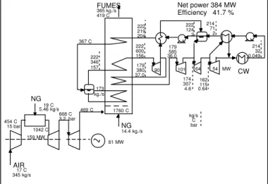
The first problem caused by the classical gas turbine is here of no concern. As the post-combustion Figure 4 : Cycle revamped with conventional gas turbine
NG CW FUMES 14.4 kg./s Net power 384 MW Efficiency 41.7 % 1760 C 222 600 156 179 585 36.0 174 307 4.6 162 115 0.64 kg/s C bar 214 32 0.049 214 71 2 222 124 2 222 219 204 367 C 222 346 157 179380 37.0 90 101 64 54 MW 365 kg./s 419 C 173 kg./s NG AIR 17 C 345 kg/s 19 C 5.46 kg/s 159 MW 1042 C 668 C 3.2 bar 469 C 454 C 15 bar 81 MW
Figure 5 : repowering with partial oxidation GT - case 1
NG AIR 17 C 100 kg/s 19 C 1.6 kg/s 45 MW 62 MW 1042 C 448 C 14.6 bar 675 C 3.17 bar NG 304 C 14.2 kg/s 1042 C CW FUMES AIR 217 kg/s 15 C Net power 402 MW Efficiency 44.7 % 1985 C 266 557 178 214 538 41.6 209 272 5.4 195 92 0.74 kg/s C bar 214 35 0.056 214 73 2 266 123 2 266 212 180 353 C 266 357 179 214343 42.6 113 98 72 64 MW 356 kg./s 188 C 274 C 278 kg./s 428 C 139 kg/s
in the boiler now uses the exhaust of the turbine as a fuel, the air preheating system can be kept. Since the air flow decreases with respect to the base case, part of it however can be modified so as to preheat the natural gas, in order to reach a sufficiently high temperature in the partial oxidation reactor.
A decrease in combustion temperature is also observed here, but in a rather limited extent. An increase of about 10% of the fumes rate is enough to compensate for the reduction in radiation rate.
The stack temperature increases from 101 to 188°C. Some investment might be considered to use this heat, e.g. to preheat the feed water.
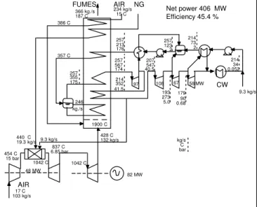
Partial oxidation gas turbine - scheme 2
An alternative scheme is shown in figure 6 : partial oxidation is carried out at a higher pressure, similar to the combustor pressure of the previous scheme. Exhaust of the reactor is expanded in two stages, first to drive the air compressor, next to generate extra power. The air preheating system can still be used and the decrease of adiabatic combustion temperature is compensated by an increase of the rate of fume. In order to reach an adequate temperature at the inlet of the partial oxidation reactor, part of the exchange area used for air preheating is converted to gas preheating service.
Some steam must be extracted from the steam turbine and injected into the reactor to avoid coke formation (this injection was not needed in the previous scheme).
Table 2 highlights the main differences between the various cases. Revamping with a partial oxidation system allows to increase the power generated by
18% and the thermal efficiency by 3 percentage points. The highest improvement is obtained with the second partial oxidation scheme.
The partial oxidation schemes only require limited changes in the steam cycle. With some investment (adding some exchange area in the boiler to preheat the boiler feed water for example), their efficiency could be further enhanced. New combined cycles can also be designed (Maréchal et al., 1997).
The classical gas turbine scheme induces the most changes to the steam cycle because of the lower temperatures in the radiation part and the subsequent decrease of the heat load of the boiler. The global efficiency slightly drops. As stated above, such an Figure 6: repowering with partial oxidation GT - case 2
AIR 17 C 103 kg/s 48 MW 82 MW 1042 C 454 C 15 bar 837 C 6.85 bar NG 440 C 19.3 kg/s 1042 C CW FUMES AIR 234 kg/s
15 C Net power 406 MWEfficiency 45.4 %
1900 C 257 567 174 207 547 40.5 193 273 5.0 179 90 0.68 kg/s C bar 214 34 0.052 214 73 2 257 123 2 257 213 176 357 C 257 355 175 214352 41.5 97 108 67 58 MW 366 kg./s 187 C 386 C 246 kg./s 428 C 132 kg/s 9.3 kg/s 9.3 kg/s
Table 2 - Comparison between the 4 technologies
Base Gas turbine Partial
oxidation -1 oxidation -2 Partial
total natural gas rate kg/s 17.5 19.8 19.4 19.3
steam rate injected in the Oxipar reactor kg/s 0 9
fumes rate out of the burner kg/s 322 365 357 366
power for the compressor MW 0.0 159.1 55.3 47.5
power of the power turbine MW 0.0 81.3 61.7 82.5
power of the HP turbine MW 97.4 89.8 97.8 96.9
power of the MP turbine MW 114.4 101.3 112.8 107.8
power of the LP1 turbine MW 73.4 64.2 72.4 67.2
power of the LP2 turbine MW 65.7 54.2 64.2 58.2
power of the steam turbines MW 351.0 309.5 347.2 330.2
electric net power MW 344.0 384.4 402.1 406.3
thermal efficiency % 42.4 41.7 44.7 45.4
adiabatic combustion temperature °C 2137 1760 1985 1900
stack temperature °C 101 419 188 187
temperature HP superheated steam °C 546 600 557 567
pressure at the inlet of the HP turbine bar 180.3 155.8 178.2 174.2
pressure at the outlet of the HP turbine bar 43.4 37.0 42.6 41.5
pressure at the outlet of the MP turbine bar 5.5 4.6 5.4 5.0
pressure at the outlet of the LP1 turbine bar 0.76 0.64 0.74 0.68
pressure at the outlet of the LP2 turbine bar 0.056 0.049 0.055 0.052
cost in natural gas (3.9 ECU/GJ) kECU/year 11750 9500 9000
benefit in electricity (14.3 ECU/GJ) kECU/year 16000 23000 24667
benefit in comparison with the Ref-1 case kECU/year 4250 13500 15667
Investment kECU 15488 12376 14142
Pay-out time year 3.6 0.9 0.9
implementation is not fully realistic, so that extensive modifications of the boiler are to be considered.
What is also important to note is that the size (and power) of the gas generator (system compressor, burner, drive turbine), is about three times smaller with the partial oxidation schemes than with the classical gas turbine. This reduced investment will however be partly balanced by the cost of the partial oxidation reactor system and the change of burners.
Our preliminary estimation of investment leads to a significant advantage of the partial oxidation schemes, with simple pay back calculation times of about 1 year.
One can therefore conclude that repowering existing power plants seems far more advantageous with partial oxidation gas turbines than with classical gas turbines : higher efficiencies and load, limited modification of the steam cycle and of the boiler, and therefore most probably limited investment.
METHODOLOGY FOR PROCESS REVAMP
# $ & $ ' %&$
' &%&- $ % ! & "&% #&" ' ( % ' "& $ % , "$ !% - )$ + ' $ - 2&$ 0 $
' % #$ # 6 , # ! & 3
! #& $ # & / , # & # , ' " ( $ & & $, %* 1 , " * + % ! , & ' % #$ + - ". )$%& ' ( % %&$ $ ( - &# , " $ * # , $ %* &"& # * 3 & ! #& $ ' %! %- & # %& &$ $ ) $ ' "& $.
- , "&$ - " , " * + &" &$ & #&% !, ""3 $, $ % ' % , # &"" ! #& $ ' - &0 & &"" ( $ ' % #$ ( $ , !! # $ &##, % /* $$ % $ & 7 8 1 $ + &% &$ ! ' "& $ ' %! %- & # ( $ % ' #$ $ & 3
# & $ ' % # 0 * $ ! % $
- &" ' %&$ # $ & ! % ' &%$ &" " & .
&# + $ &"0 $ - " - , $ * * & )' % - $&" &$&. ( + % %&( ' "& $ - & , % - $ &% $ % #$"3 , &* " ! % $, - " ' &%&- $ % 0 * #&, - & , % - $ &% &!! #$ * 3 %& - %% % 0 % &##, % " - $ 0 $ ' % # + % &$ $ & 3
$&$ 0 & "&% , - * % ! $&$ + &% &* " &% $ - & , % .
+ %# - $ ' % * " - 0 , " , & &$& % # # " &$ - " ! $ ' "& $. &$& % # # " &$ , & $ ! # $%& $ 6 , &$ & &"" &+ & "&* "
)' % - $&" &$& $ * , " & * %+ % ! $ ' "& $ $&$ . % # # " % + &" &$ + &", ! &"" ' % # + &% &* " * $& * 3 "+ & # $%& - - 2&$ ' % * " -min . . X,Y s t (X X*)T.W.(X X*) F(X, Y) = 0 − − ( %
9 &% - & , % $&$ + &% &* " / 2 - 1:
9 ; $ - & , % - $ &%%&3 :
9 &% , - & , % $&$ + &% &* " / 2 1:
9 & ( $ 6 , &% - &$% )0 $&5 & $ + % ! $ # + &% & # - &$% ) !
;.
9 $ $ ! &"" # $%& $ 6 , &$ $ &$ % ' % $ $ ' % # - " / 2 ' 1.
The redundancy of the measurement data set is : R=p-n
The commercial data reconciliation package we use (Belsim 1997) allows to analyse the structure of the measurement set, and to check if the system is observable, before proceeding to the problem solution. It also suggest additional measurement points (or good estimates if nothing else can be obtained). It performs sensitivity analysis and estimates the accuracy of all validated results based on assumed accuracy of the measurement set (Heyen et al., 1996 b). The resulting estimates of state variable X and Y are consistent with all constraint equations (mass and energy balances, phase equilibrium conditions). Thus carrying out data reconciliation provides all information needed to perform model identification on a safe ground, since consistent values are obtained for all state variables (directly measured or not).
Parameter identification can then be performed separately for each unit of the model. Tuneable parameters such as efficiency coefficients and heat transfer coefficients are selected to match the model predictions with the reconciled variables.
The resulting tuned model perfectly matches validated observations and can be used to perform simulations of any operating condition of the original plant. A suitable reference case is thus available to assess the performance of any plant modification.
A CASE STUDY
A demonstration site has been selected to further investigate the potential of partial oxidation gas turbine. Detailed information has been obtained about an existing power plant located in St Petersburg (Russia) and built in the seventies. The plant generates electricity, but also delivers hot water for district heating. It features three parallel production lines, for which capacity increase is sought. A project to modify one of the steam generator by adding a gas turbine is already under way. Thus the site would allow comparison of three different technologies operating in parallel : 1.- a conventional Rankine cycle with superheat and water preheating with steam extraction, 2.- a combined cycle obtained by topping a modified steam generator with a gas turbine, 3.- a combined cycle obtained by coupling a partial oxidation gas turbine and the same steam generator.
The main cycle characteristics of the existing cycle to be modified are given in table 3.
Measurements on the present plant performance have been supplied for different operating conditions (summer and winter condition, operation with natural gas or fuel oil, full or partial load). Since raw measurements are known to be plagued with errors, data reconciliation techniques have been applied, to obtain reliable energy balances, and to estimate unmeasured process variables that are needed to assess the performance of individual units (heat exchangers fouling factors, expanders efficiency).
The modelling of the system has been divided into two separate tasks : the water-steam cycle and the furnace.
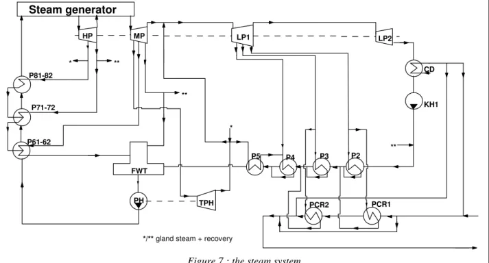
The water-steam model is represented by a system of 352 equations. Unit operations considered in the model are (see figure 7) :
- for the condensate lines : - condenser CD; - feed water pump KH1;
- injections recovered from gland steam; - preheaters (4 heat exchangers P2 to P5). - for the feed water lines :
- feed water drum FWT; - feed water pump PH;
- steam turbine driving the pump TPH; - feed water preheaters (units P6,P7,P8) - for the steam generator :
- a black box model (heat balance only), details
being considered in the detailed boiler model. - for the turbine section :
- high pressure turbine HP (2 stages with extraction for water preheat);
- medium pressure turbine MP (4 stages with extraction for water preheat)
- low pressure turbine LP (4 stages with 3 extractions for water preheat and district heating); - gland steam leaking out the turbines is collected and used for water preheating just after the condenser and in exchanger P5;
- district heating :
- 2 heat exchanger PCR1 and PCR2.
Data reconciliation allowed to identify completely the state of each stream (temperature, pressure, enthalpy, mass flow). Measurement redundancy is well distributed in the steam system. The only area where measurements were lacking was the gland steam collection system.
From these information, it was straightforward to calculate performance parameters, such as the heat transfer coefficients of each heat exchanger and the isentropic efficiency of each expansion stage in the turbines.
In some heat exchangers (P6, P7, P8), transition from 2-phase to 1-phase flow is observed (condensation and subcooling) and information was lacking to identify both heat transfer coefficients. In this case, the value of the condensing heat transfer coefficient was fixed based on an empirical correlation, and the area used for condensation was calculated by the program; this allowed to estimate the remaining area, used for subcooling, and the corresponding coefficient could thus be identified.
To characterise each turbine stage, a flow coefficient k was also identified, that relates the steam flowrate G1 to the inlet and outlet pressures, and to
the inlet specific volume VG : k = G1
P12 P22 .VG P1.
−
Table 3 : main parameters of the power plant Maximum steam pressure 250 bar Maximum steam temperature 545 °C Steam pressure after reheat 27.5 bar
Reheat temperature 545 °C
Water preheat using drawoff 10 stages Condenser pressure 0.087 bar
Operation Fuel oil Gas
Boiler load 595 MW 745 MW
Electricity production 205 MW 247 MW District heating (water 75°C) 260 MW 430 MW
** ** * ** P81-82 P71-72 P61-62 HP MP LP2 FWT TPH P2 P3 P4 P5 PCR1 PCR2 KH1 CD PH
*/** gland steam + recovery *
Steam generator
LP1
This coefficient was assumed to stay constant when the model was extrapolated in simulation mode, to predict the process response to any variation of operating conditions.
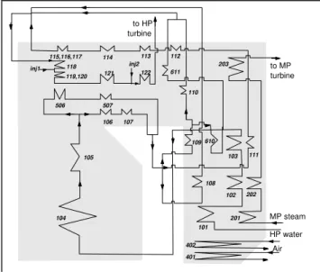
The steam generator model is represented by a system of 213 equations. Unit operations considered in the model are (see figure 8) :
- combustor :
- burner model assumes complete combustion; either natural gas or fuel oil can be handled; - heat transfer by radiation :
- vaporisation section (104, 105, 106,107,506,507)
- heat transfer by convection : - steam superheater (111-122); - MP steam reheater (201, 202 ,203); - economisers (101, 102, 103) - steam temperature control :
- water injections to desuperheat steam; - sections to model the air preheater (401, 402).
Measurements were missing for many streams. In particular, little was available about the temperature profile in the combustion gas channel. The gas distribution in parallel heat exchangers had to be estimated based on design values.
Data reconciliation allowed to identify completely the state of each stream (T,P, mass flow, and composition). From this information, it was straightforward to calculate all performance parameters, such as the heat transfer coefficients.
In the convection section, we used an approach similar to the one detailed for the steam circuit. In the radiation section, we assumed the following relationship to hold :
Qrad = Kr Tgas4 −Tsteam4
The Kr adjustable coefficient lumps together the
contributions of transfer area, emissivity and shape factors for each section where radiative exchange takes place. The lack of experimental data does not allow to fit more parameters.
An overall model of the power plant is obtained by merging both sections. The resulting model is made of 581 equations. Among the 813 state variables, 255 are measured and 159 are set constant
as specifications. The value of 399 unmeasured variables can be calculated by the validation algorithm, and the problem redundancy is 182. Solution of the data reconciliation problem is obtained using a large scale SQP solver (Kyriakopoulou et al., 1996)
DIFFICULTIES IN MODEL DEVELOPMENT
A modern power plant is a highly integrated unit. Model development using a sequential approach is difficult, since the number of recycle streams is large. Simulation software based on a global equation solving approach are definitely superior.
Modelling heat exchangers in the steam superheating section posed several difficulties : several bundles are located in series along the steam path, but are located in parallel in the combustion gas channel. The combustion gas flow rate that exchanges heat with each of those tube bundles is almost impossible to estimate. Ideally, this should be identified from data reconciliation. However temperature measurements are not available between all sections. No reliable combustion gas measurement is available either. Furthermore, radiative heat transfer is likely to contribute significantly in this high-temperature zone.
USE OF CAPE TOOLS
The rating simulation allows to predict the variation of the process performance, both under varying operating conditions (load factors, seasonal demand) and for different process modifications. The data reconciliation model can also be used to perform rating simulation, by handling specifications as pseudo measurements, and setting the value of performance parameters identified in the previous step. We checked the model validity by comparing the model response for different load scenarios to the measurements.
A sensitivity analysis has been performed, especially to verify the flexibility of operation under partial load (off-design). Reverting to the use of natural gas (the current fuel) is investigated as a back-up solution, in case of failure of the gas turbine or the partial oxidation system.
Another implementation under study combines two parallel partial oxidation gas turbines with a single steam generator and allows to achieve high efficiency under a wide range of operating conditions, with a significant increase of electricity production.
CONCLUSIONS
The study reveals how techniques that have been developed for the analysis and synthesis of chemical processes can also be applied efficiently to large scale thermo-mechanical processes and address challenges in energy conservation.
Collaboration is needed between mechanical engineers, power plant operators, turbine designers and chemical engineers. Cross-fertilization between engineering teams who tend to live in separate worlds bring significant benefits in the development of innovative technologies. 104 105 506 507 106 107 109 108 101 102 103 111 112 113 114 115,116,117 118 119,120 121 122 inj2 inj1 610 110 611 Air HP water MP steam to HP turbine 201 203 202 to MP turbine 402 401
REFERENCES
Belsim s.a., VALI III users guide, Belsim, Allée des Noisetiers, 1, B-4031 Angleur Belgium, (1997)
Heyen G., J. Ribesse, B. Kalitventzeff, Exergy Analysis of advanced thermal cycles suitable for upgrading existing Power Plants, presented at CHISA'96 Congress, Prague, (1996 a)
Heyen G., E. Maréchal, B. Kalitventzeff, Sensitivity calculations and variance analysis in plant measurement reconciliation, Comp. Chem. Engg, vol. 20S, pp 539-544 (1996 b).
Kyriakopoulou D., B. Kaliventzeff, Validation of measurement data using an Interior Point SQP. Comp. Chem. Engg, vol. 20S, pp 563-568, (1996).
Maréchal F., M.N. Dumont, B. Kalitventzeff, Pinch point methods in optimization of advanced combined cycles, International. Conference on Power Stations, Liège (Belgium) 13-15 October (1997)
OXIPAR, Patent publication n°1009707A6, Système énergétique thermique à turbine à gaz avec oxydation partielle catalytique de combustible (1977)