1 INTRODUCTION
Since many decades, researchers are contributing regularly to the development of efficient design formulae for the design and the verification of steel structural columns subjected to combined bending moments and axial forces. Recently, further to sev-eral years of intensive research and discussions within the Technical Committee 10 “Stability” of the European Convention for Constructional Steelwork (ECCS), new formulae have been de-veloped and included in the EN version of the Eu-ropean Norm Eurocode 3 Part 1-1 (EN 1993-1-1, 2005).
These formulae, the background and the mode of application of which are described in a recent ECCS publication (Boissonnade et al. 2006), have been validated by means of extensive comparisons with more than 20.000 numerical simulations and 250 to 300 experimental tests. Their accurate and their much less conservative character than the ones of the previous version ENV 1993-1-1 (1992) have also been widely demonstrated.
In the design guide n°2 (DG2) of CIDECT (Comité International pour le Développement et l’Etude de la Construction Tubulaire), an explicit reference is made to Eurocode 3 ENV for the veri-fication of the resistance and the stability of beam-columns with hollow sections. In the framework of the forthcoming revision of DG2, it should be logi-cally decided to refer to the newly developed EN formulae.
It has however to be recognized that the new EN formulae have been validated mostly through com-parisons with results of experimental tests and nu-merical simulations carried out on columns with open sections, and only with a very limited number of experimental tests on tubular columns. The question may therefore be raised to know whether the new formulae are adapted to the tubular col-umns. The reply to this question is brought through a recently finalised CIDECT-funded project devot-ed to the application of the new EC3 formulae to columns with tubular sections.
2 METHODOLOGY
In fact, two aspects have to be considered in beam-column interaction formulae: the resistance of the cross-sections and the stability of the member (the member effects). The first aspect strictly depends on the resistance class of the cross-sections while the second one relate to the member slenderness. EC3 suggests plastic resistance values for class 1 or 2 cross-sections and elastic ones for class 3 or 4 cross-sections.
In the new EC3 design formulae, the way of tak-ing into account member effects is rather accurate and for sure is similar whatever the cross-section class and shape. As a result, it can be stated that the degree of accuracy and safety of the new EC3 beam-column formulae widely depends on the “in formulae embedded” cross-sectional resistance cri-teria.
The present paper mainly focuses on how the cross-sectional resistance aspects are covered in the
Application of the new Eurocode 3 beam-column formulae
to tubular construction
L. Ly & J.P. Jaspart
University of Liege, Belgium
K. Weynand
Feldmann + Weynand Ingenieure, Aachen, Germany
ABSTRACT: New design formulae for the stability of structural members subjected to combined bending moments and axial forces (so-called beam-columns) have been recently developed and included in the EN version of the European Norm Eurocode 3 Part 1-1 (EC3). It has however to be recognized that these formulae have been validated mostly through comparisons with results of experimental tests and numerical simulations carried out on columns with open sections. The question may therefore be raised to know whether the new formulae are adapted to tubular columns with a similar degree of accuracy and safety than for open section columns. The aim of the paper is to indicate how present EC3 formulae fit with the available results on tubu-lar columns, and then to suggest improvements of the formulae when applied to the latter.
case of columns with class 1 and 2 rectangular hol-low sections (RHS).
Besides that, Eurocode 3 presents two sets of beam-column formulae - Annex A (Method 1) and Annex B (Method 2) - and it is up to each country to decide whether the first one, the second one of both of them are to be recommended. The key words on which Method 1 has been developed are “generality”, “transparency”, “consistency” and “accuracy”. The corresponding interaction formu-lae have so been derived as far as possible on theo-retical bases so as to be able to cover any loading, i.e. axial compression only, axial compression and monoaxial bending or biaxial bending, with or without lateral torsional buckling ... In addition, they have been developed in such a way that each coefficient in the formulae represents a single physical effect.
But on the other hand, as already said, almost all these coefficients have been derived for members with I or H cross-sections. Therefore the objectives of the present paper are twofold:
• indicate how present EC3 formulae fit for RHS columns;
• suggest improvements of the formulae when applied to RHS members;
3 APPLICATION OF THE NEW EUROCODE 3 METHOD 1 FORMULAE TO RHS
COLUMNS
3.1 Method 1 stability formulae
EC3 distinguishes “members susceptible to tor-sional deformations” from “members not suscepti-ble to torsional deformations” ones. In Method 1, no torsional deformations occur if:
t y
I ≥I (1)
where It and Iy represent respectively the torsional
and flexural (strong axis) rigidities of the cross-section.
In the opposite case (It<Iy), lateral torsional
buckling (LTB) effects have to be considered, ex-cept if efficient restraints prevent them from devel-oping. An expression is suggested in the EN 1993-1-1 Annex A to check the efficiency of the re-straints.
Usually, for RHS cross-sections, the above cri-terion is satisfied; so all the LTB effects can be ne-glected. Accordingly, a RHS column submitted to axial forces and bending moments has to be veri-fied by Eqs. (2) and (3) as follows:
, , , , , , , , , * 1 (1 / ) (1 / ) my y Ed mz z Ed Ed y y pl Rd Ed cr y yy pl y Rd Ed cr z yz pl z Rd C M C M N N µ N N C M α N N C M χ + + ≤ − − (2) , , , , , , , , , * 1 (1 / ) (1 / ) my y Ed mz z Ed Ed z z pl Rd Ed cr y zy pl y Rd Ed cr z zz pl z Rd C M C M N N µ β N N C M N N C M χ + + ≤ − − (3)
where NEd, My,Ed and Mz,Ed are the design values of
the compression force and the maximum moments along the member about the y–y and z–z axes, re-spectively; Npl,Rd, Mpl,y,Rd, Mpl,z,Rd are the design
plastic resistances to the normal force and bending moments;
χ
y andχ
z are the reduction factors due toflexural buckling under pure compression; Cmy and Cmz are the equivalent uniform moment factors; Ncr,y and Ncr,z are the Euler elastic critical loads;
y
µ and µzare defined as follows
, , 1 / 1 / Ed cr y y y Ed cr y N N N N µ = −χ − (4) , , 1 / 1 / Ed cr z z z Ed cr z N N N N µ χ − = − (5)
α
* andβ
* are plasticity factors accounting for thecross-sectional biaxial bending resistance interac-tion (for Class 1 and 2 cross-secinterac-tions):
* 0, 6 z y w w α = (6) * 0, 6 y z w w β = (7)
Cyy, Cyz, Czy and Czz are also interaction factors; the
cover the plastic interaction in the cross-section be-tween axial compression and bending moment (again for Class 1 and Class 2 cross-sections):
(
)
2(
2)
, max max , 1, 6 1 1 2 Ed el y yy y my y Rd pl y W N C w C w λ λ N W = + − − + ≥ (8)(
)
2 max2 * , 5 , 1 1 2 14 mz Ed el z yz z z Rd pl z W C N C w w N W λ α = + − − ≥ (9)(
)
2 2 max * , 5 , 1 1 2 14 my Ed el y zy y y Rd pl y C N W C w w N W λ β = + − − ≥ (10)(
)
2(
2)
, max max , 1, 6 1 1 2 Ed el z zz z mz z Rd pl z W N C w C w λ λ N W = + − − + ≥ (11)All these plasticity factors tends to 1,0 for Class 3 or 4 cross-sections).
It is also important to notice that besides this stability check, the resistance check of the member end sections has always to be verified.
3.2 Application to RHS stub columns under monoaxial compression and bending moment
a) Format of the Cij factors
Under axial compression and monoaxial bending, the stability formulae reduce to simpler expres-sions. For the particular case of strong axis bending they write: , , , , , 1 1 1 my y Ed Ed Ed y pl Rd yy pl y Rd y cr y C M N N N C M N χ + −χ ≤ (12) or 1 1 1 my y y y yy C m n n C χ + −χ ≤ (13)
where n = NEd/Npl,Rd and my = MEd/Mpl,y,Rd.
As said before, plasticity effects (M-N cross-sectional resistance interaction in Class 1 or 2 cross-sections) are covered by the factors Cij (Cyy in
this case). These coefficients fully play their role in stub columns where no member instability occur and failure is associated to the plastic resistance of the most loaded cross-section along the column. In more slender columns, the amount of plasticity which develops at column failure in the most load-ed cross-section along the column will obviously depend on the slenderness of the column (for in-stance, no plasticity will occur if the column slen-derness is high as, in such a the column will fail by pure elastic instability. These Cij factors are so
composed of two parts:
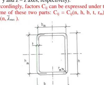
• a “cross-section” part relative to cross-section resistance; it is expressed as a function of the geometry of section, i.e. parameters h, b, t, rm
(Figure 1);
• a “member” part relative to member slender-nessλmax(maximum value of λy and λz, the
rel-ative slenderness for column buckling about y – y and z – z axes, respectively).
Accordingly, factors Cij can be expressed under the
some of these two parts: Cij = Cij(n, h, b, t, rm) +
Cij(n,λmax).
Figure 1: Geometry of a Rectangular hollow section (RHS)
In case of stub members, Eq. (12) should be re-duced to an expression equivalent to the resistance of cross-section; when the member slenderness
tends to zero, then Cmy → 1, χy → 1, and
(
,)
1 / 1−χyNEd/Ncr y →1, and then Eq. (12) becomes
, , , , 1 y Ed Ed pl Rd yy pl y Rd M N N +C M ≤ (14) , or my ≤ −(1 n C) yy (15) , with
(
)
, , 1 2 1 el y yy y pl y W C w n W = + − ≥ (16), the part Cij(n,λmax) = 0.
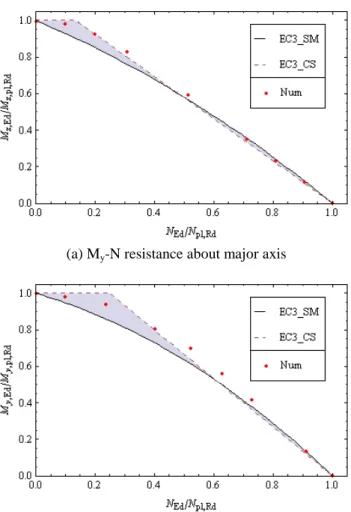
In Eq. (16), the factor 2 is the theoretical value that is derived from the exact M-N interaction for full rectangular cross-sections (Boissonnade et al.). Let’s verify the validation of this factor through following comparative graphs performed for RHS 160x80x6.3 (Figure 2) and RHS 75x75x3 (Figure 3):
• “EC3_SM” curve represents stub member Mi-N
resistance following EC3;
• “EC3_CS” curve represents cross-section Mi-N
resistance following EC3, section §6.2.9.1; • “Num” curve represents Mi-N resistance carried
out by numerical simulations.
It is to notice that numerical simulations have been performed, by a home made FEM Finelg, with exactly equivalent conditions on material and restraint as in the formulae. Steel material was as-sumed elastic perfectly-plastic and defined by the elastic modulus E = 0.2x10⁶ N/mm², the Poisson coefficient υ = 0.3, and a value of elastic limit fy.
The comparative study allows to following statements:
• The proposed formulae of EC3 for cross-section resistance do not very fit with RHS. The given figures show a quite good approximation for Mi -N resistance at high compression level
(NEd/Npl,Rd > 0.7), but obviously no more
pre-cise at lower compression level, especially for
Mi-N resistance of minor axis (Figure 2b).
• The proposed formulae of EC3 applied to RHS stub members get a quite good approximation at high compression level (NEd/Npl,Rd > 0.6), an
considerable conservative estimation at lower compression level, also especially for Mi-N
re-sistance of minor axis (Figure 2b).
Then, the factor 2 of Eq. (16) should be im-proved such as first to exploit more the plastic ca-pacity of the sections and then to reconcile both re-sistance criteria relative to cross-section and stub member.
(a) My-N resistance about major axis
(b) Mz-N resistance about minor axis
Figure 2: RHS 160x80x6.3, Mi-N cross-section and stub
member resistance, following EC3 and numerical simulations
Figure 3: RHS 75x75x3, Mi-N cross-section and stub member
resistance, following EC3 and numerical simulations
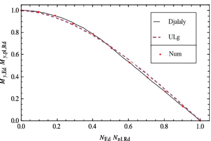
b) Djalaly formula for Mi-N cross-section re-sistance
Djalaly H. et al. proposed following formulae to calculate My-N cross-section resistance (or Mz-N
by exchanging b and h) of a RHS: 2 1 1 , when 0 1 y m f n n γ γ = − ≤ ≤ + (17) 2 (1 ) , when 1 1 y m n f γ n γ = − < ≤ + (18) , with 2 1 (1 ) (2 2 ) f γ γ +γ ω = + + (19) 2 (1 )(1 ) 1 / 2 f ω γ ω γ + + = + + (20) , and h 2t b γ = − (21) 2 t h t ω = − (22)
Again, the proposed formulae were verified with results of numerical simulations. Figure 4 and Figure 5 report results carried out for RHS 160x80x6.3 and RHS 75x75x3, respectively: • “Djalaly” curve represents Mi-N cross-section
resistance following Djalaly formulae;
• and “Num” curve represents Mi-N resistance
carried out by numerical simulations.
It is obviously seen that the proposed formulae gives a very good approximation to the numerical ones. They should be used to improve the “cross-section resistance” part in the interaction formulae of EC3. 0.0 0.2 0.4 0.6 0.8 1.0 0.0 0.2 0.4 0.6 0.8 1.0 NEdNpl,Rd M y, E d M y, pl ,R d ULg Djalaly 0.0 0.2 0.4 0.6 0.8 1.0 0.0 0.2 0.4 0.6 0.8 1.0 NEdNpl,Rd M y, E d M y, pl ,R d Num
(a) My-N cross-section resistance about major axis
0.0 0.2 0.4 0.6 0.8 1.0 0.0 0.2 0.4 0.6 0.8 1.0 NEdNpl,Rd Mz, E d Mz, pl ,R d ULg Djalaly 0.0 0.2 0.4 0.6 0.8 1.0 0.0 0.2 0.4 0.6 0.8 1.0 NEdNpl,Rd Mz, E d Mz, pl ,R d Num
(b) Mz-N cross-section resistance about minor axis
Figure 4: RHS 160x80x6.3 Mi-N cross-section resistance,
0.0 0.2 0.4 0.6 0.8 1.0 0.0 0.2 0.4 0.6 0.8 1.0 NEdNpl,Rd M y, E d M y, pl ,R d ULg Djalaly 0.0 0.2 0.4 0.6 0.8 1.0 0.0 0.2 0.4 0.6 0.8 1.0 NEdNpl,Rd M y, E d M y, pl ,R d Num
Figure 5: RHS 75x75x3 Mi-N cross-section resistance,
fol-lowing Djalaly and numerical methods
c) Proposal of University of Liege (ULg) for the factor “2”
It is also obviously seen that a Mi-N cross-section
resistance formula has to have a similar form than the one of Eq. (15) in order to be able to be im-planted into the interaction formulae of EC3. Ac-cordingly a calibrated formula (ULg’s formula) has been developed, based on Djalaly formulae as fol-lows: 2 1 2 (1 )(1 ) y m ≤ −n +g n+g n (23) With, 2 1 2(1 ) (1 ) (1 2 )(2 2 ) g γ ω γ+ γ+ ω = + + + (24) , and 2 2 (1 ) ( 1 2 ) (1 2 )(2 2 ) g γ γω γ + γ − +γ ω = + + + (25)
The factor 2 in the coefficient Cyy (and Cyz)
should be replaced by the following factor ay:
1 2 1 y y g g n a w + = − (26) , and then
(
)
, , , 1 1 Ed el y yy y y pl Rd pl y W N C a w N W = + − ≥ (27)In Figure 4 and Figure 5, a quite good approxi-mation of ULg’s curves to the numerical ones vali-dates the proposed formulae. Furthermore, with the same purpose, the factors 2 in coefficients Cyz and
Czz should be also replaced by a factor az given by
Eq. (30): 2 * * 1 1 z z g g n a w + = − (28)
, with g1* and g2* calculated following Eqs (24)
and (25), but by exchanging b and h.
3.3 Application to RHS stub columns under
biaxial bending
a) Verification of α* and β*
When the axial force NEd is negligible and the
member length is very small, and then the influ-ence of instability vanishes, the problem reduces to
cross-section resistance affected by the interaction of biaxial bending. Eqs. (2) and (3) are reduced to stub member formulae under biaxial bending:
* 1
y z
m +α m ≤ (29)
, and β*my+mz ≤1 (30)
, while EC3 proposes another formula specifically to cross-section resistance as follows:
1
y z
mα+mβ ≤ (31)
, my and mz are respectively My,Ed/Mpl,y,Rd and
Mz,Ed/Mpl,z,Rd, and α and β, the factors depending
of cross-sectional shape to take into account plastic effects (
α
,β
≥ 1). According to the point§6.2.9.1(6) of EC3, 2 1.66 ; but , 6 1 1.13n α β= = α β≤ − (32)
It can be seen that
α
* andβ
* should be derivedfrom the linearization of Eq. (31) (Figure 6) to be able to keep the linear form of the interaction for-mulae (29) and (30).
Figure 6: Biaxial bending interaction
The proposed
α
* andβ
* in Eqs. (6) & (7) areobviously suitable for I or H profile members, but again maybe not for RHS members. The verifica-tion was performed through following comparative graphs on RHS 160x80x6.3 (Figure 7a) and RHS 75x75x3 (Figure 7a):
• “EC3_SM” curve represents stub member My -Mz resistance following Eqs. (29) & (31);
• “EC3_CS” curve represents cross-section My-Mz
resistance following Eq. (31);
• “Num” curve represents My-Mz resistance
car-ried out by numerical simulations. That allows to following statements:
• A good agreement between “EC3_SM” and “Num” curves means that the proposed formu-lae of EC3 for cross-section resistance are fit for RHS.
• A considerable lack between “EC3-CS” and “Num” curves means that the factors α* and β*
should be improved to exploit more the plastic capacity of RHS. 0.0 0.2 0.4 0.6 0.8 1.0 0.0 0.2 0.4 0.6 0.8 1.0 My,EdMy,p l,Rd Mz, E d Mz, pl ,R d Num 0.0 0.2 0.4 0.6 0.8 1.0 0.0 0.2 0.4 0.6 0.8 1.0 My,EdMy,p l,Rd Mz, E d Mz, pl ,R d EC3_CS EC3_SM (a) RHS 160x80x6.3 0.0 0.2 0.4 0.6 0.8 1.0 0.0 0.2 0.4 0.6 0.8 1.0 My,EdMy,p l,Rd Mz, E d Mz, pl ,R d Num 0.0 0.2 0.4 0.6 0.8 1.0 0.0 0.2 0.4 0.6 0.8 1.0 My,EdMy,p l,Rd Mz, E d Mz, pl ,R d EC3_CS EC3_SM (b) SHS 75x75x3
Figure 7: My-Mz cross-section resistance following EC3 and
numerical methods
b) Proposal of University of Liege (ULg) for α* and β*
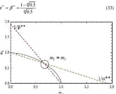
Based on Eq. (31), new factors α* and β* (now called
α
** andβ
**) have been derived by bi-linearapproximation. Given the symmetry of the problem under the non dimensional my-mz form, α** should
be equal to β** when my equal to mz (Figure 8).
Then ** ** 1 0.5 0.5 α α α =β = − (33)
Figure 8: Biaxial bending interaction under my-mz form
Figure 9 again demonstrates that the new de-rived α** and β** fit well with RHS 160x80x6.3 and RHS 75x75x3, through “ULg_SM” curves.
0.0 0.2 0.4 0.6 0.8 1.0 0.0 0.2 0.4 0.6 0.8 1.0 My,EdMy,p l,Rd Mz, E d M z, pl ,R d Num 0.0 0.2 0.4 0.6 0.8 1.0 0.0 0.2 0.4 0.6 0.8 1.0 My,EdMy,p l,Rd Mz, E d M z, pl ,R d EC3_CS ULg_SM (a) RHS 160x80x6.3 0.0 0.2 0.4 0.6 0.8 1.0 0.0 0.2 0.4 0.6 0.8 1.0 My,EdMy,p l,Rd Mz, E d Mz, pl ,R d Num 0.0 0.2 0.4 0.6 0.8 1.0 0.0 0.2 0.4 0.6 0.8 1.0 My,EdMy,p l,Rd Mz, E d Mz, pl ,R d EC3_CS ULg_SM (b) SHS 75x75x3
Figure 9: My-Mz cross-section resistance following ULg
pro-posal and numerical method
3.4 Application to RHS long columns
The proposed improvements on parameters Cij, and
on α* and β* have been verified again with long members. Then, comparative study was performed on two profiles:
• hot forming RHS 160x80x6.3, radius rm equal
to 9.4 mm, imperfection factor α (under com-pression) equal to 0.21,
• and cold forming SHS 75x75x3, rm = 4.5 mm, α
= 0.49.
For simplicity’s sake, bending moments were as-sumed uniform, i.e. ψy = 1 or ψz = 1; and free end
rotations in two directions y-y and z-z.
a) Members under 2D axial compression and bending moment (My,Ed-NEd or Mz,Ed-NEd)
Figure 10, Figure 11 and Figure 12 presents differ-ent interaction curves carried out by differdiffer-ent methods:
• “EC3”, EC3 following Eqs. (2) and (3),
• “ULg”, ULg proposal with improvements on Cij
and on α* and β*,
; and for different member slenderness (λy or λz)
ranging from 0.0 to 2.0.
The comparative study allows to following statements:
• When the column is highly slender (λy or λz >2.0), both EC3 and ULg curves joint together and present elastic behaviour, • Compared with numerical simulations, ULg
curves overestimates a bit of plastic effects of slender members, whereas EC3 curves underes-timate the latter. It means the member part with-in Cij should be also improved to fit better with
RHS.
Figure 10: Hot forming RHS 160x80x6.3 (rm = 9.4 mm)
un-der only My,Ed and NEd, ψy = 1
Figure 11: Hot forming RHS 160x80x6.3 (rm = 9.4 mm)
un-der only Mz,Ed and NEd, ψz=1
Figure 12: Cold forming RHS 75x75x3 (rm = 4.5 mm) under
only My,Ed and NEd, ψy=1
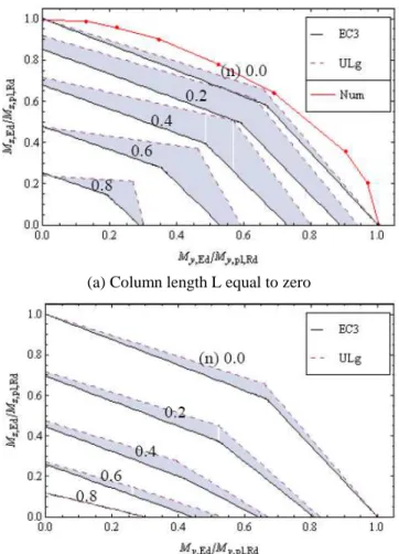
b) Members under axial compression and bending moments NEd, My,Ed and Mz,Ed
Again, Figure 12 and Figure 13 present different interaction curves carried out by EC3, ULg formu-lae and numerical simulations, with different level of axial force n (NEd/Npl,Rd) from 0.0 to 1.0, and
with two member lengths L equal to zero and 3890.05 mm.
Similar comments to the last point should be obtained with the given results:
• When the column is highly slender, both EC3 and ULg curves joint together and present elas-tic behaviour,
• Compared with numerical simulations, ULg curves should overestimate a bit of plastic ef-fects of slender members, whereas EC3 curves underestimate the latter.
There are certainly works on improvement of parameters Cij, especially its member part such as
to fit better to RHS. Furthermore, more numerical simulation and collection of experimental data should be forthcoming to be able to validate the proposal.
Whatever, it can be seen that the proposed mod-ification on Cij and on α* and β* can increase
ef-fectively resistance of RHS members that is still much conservative following the actual EC3.
(a) Column length L equal to zero
Figure 13: Hot forming RHS 160x80x6.3 (rm = 9.4 mm),
ψy=1, E=0.2 106 N/mm², fy=410 N/mm²
4 CONCLUSIONS AND PERSPECTIVES The paper presents how to apply the new Eurocode 3 beam-column column formulae to tubular con-struction. Investigations have been limited only within class 1 or 2 sections, and especially with RHS members.
Parameters on Cij and on α* and β* were deeply
highlighted to be able to improve the interaction formulae, being closer to the reality, and then more economic. Accordingly, improvements on Cij and
on α* and β* have been proposed. These im-provements allow increasing effectively resistance of RHS members that is still much conservative following the actual EC3. But, compared to numer-ical simulations, the proposal seems to overesti-mate a bit of plastic effects of slender members. It may be due to the member part of parameters Cij
that is not really fit to RHS members. That is may be the work in the next step.
Furthermore, more numerical simulation and collection of experimental data should be forth-coming to be able to validate the proposal.
PREFERENCES
EN 1993-1-1 (2005), "Design of Steel Structures, Part 1.1: General Rules and Rules for Building", European Com-mittee for Standardisation, Brussels.
ENV 1993-1-1 (1992), "Eucocode 3 Parite 1-1: Règles géné-rales et règles pour les bâtiments", Normalisation fran-çaise.
Djalaly H. (1975), “Calcul de la résistance ultime des barres comprimées et fléchies”, Construction Métallique, n° 4, p. 17 to p. 47.
Boissonnade N., Greiner R., Jaspart J.P. and Lindner J. (2006), “Rules for Member Stability in EN 1993-1-1”, Background documentation and design guidelines, Publi-cation n° 119 of the European Convention for Construc-tion Steel work (ECCS), Bruxelles, 2006.
Semi-Comp Project (2007), “Plastic Member Capacity of Semi-Compact Steel Sections – a more economic design”, Final report, RFCS contract n° RFSR-CT-2004-00044, 01/07/2004 to 30/06/2007.