Open Archive Toulouse Archive Ouverte (OATAO)
OATAO is an open access repository that collects the work of Toulouse researchers and
makes it freely available over the web where possible.
This is an author-deposited version published in: http://oatao.univ-toulouse.fr/
Eprints ID: 4497
To cite this version:
GOUACHE Thibault, GAO Yang, GOURINAT
Yves, COSTE Pierre. Wood wasp inspired space and earth drill. In:
Biomimetics Learning from Nature. InTech - Open Access Publisher,
Rijeka, Croatia, 2010, pp. 467-486.
ISBN 978-9-5330-7025-4
Any correspondence concerning this service should be sent to the repository
administrator:
[email protected]
Wood wasp inspired planetary and Earth drill
Thibault Gouache, Yang Gao, Yves Gourinat and Pierre Coste
0
Wood wasp inspired planetary and Earth drill
Thibault Gouache and Yang Gao
Surrey Space Centre United-Kingdom
Yves Gourinat
Institut Supérieur de l’Aéronautique et de l’Espace France
Pierre Coste
ESTEC European Space Agency
1. Introduction
The exploration of the solar system is known to be very challenging to scientists, engineers and, technicians alike. One of the most difficult engineering challenges in extra-terrestrial exploration is gaining access to sub-surface samples and data. The fact that there have only been three successful drilling missions on extraterrestrial bodies (Russian Luna missions to the Moon, American Apollo missions to the Moon and Russian Venera missions to Venus) illus-trates the high difficulty of sub-surface exploration on other planetary bodies than the Earth. However the potential scientific return of a sub-surface exploration mission is immense. For example, if we wish to detect the presence of organic molecules on Mars, we must dig through the first layers of the soil. Indeed, any organic molecule in these first layers is subject to high concentrations of oxidizing elements and is exposed to high ultraviolet fluxes which rapidly decompose it.
In this chapter, we will explain why the low gravity encountered on Mars or on the Moon and, the low mass of the probes, landers and rovers that carry drilling devices limit classical drilling techniques. Novel boring solutions optimised in mass and power consumption are thus needed for space applications. Biologists have identified the wood wasp, an insect that is capable of “drilling" into wood to lay its eggs. A low mass and low power system, like an insect, capable of drilling into wood is of the highest interest for planetary drilling and terres-trial drilling alike. The general working principle of the wood wasp drill (“dual reciprocating drilling") will be exposed and the potential benefits of imitating the wood wasp for planetary drilling will be highlighted.
Since the nature of wood is highly fibrous but the nature of extraterrestrial and terrestrial soils are not, it is necessary to adapt the wood wasp ovipositor to our target soils. A test bench to evaluate the influence of the different geometries and operational parameters was produced and is presented here. The dual reciprocating drilling experimental results obtained
on this test bench are also highlighted. They should lead to a new and enhanced model and comprehension of dual-reciprocating-drilling.
2. The challenges of drilling in extra-terrestrial bodies
2.1 Why drill in planetary bodies?
Drilling and subsurface exploration is called upon regularly in space missions. It is needed for producing samples for scientific payloads or sample return missions. But sampling is not the only reason for creating a borehole. The existence of the borehole allows a robot or a human to place captors in it for in-situ experimentation: for instance a neutron probe for water detection, an amino-acid bio-marker detection Skelley et al. (2005) or a thermal sensor for temperature gradient and flux evaluation Komle, Htter, Kargl, Ju, Gao & Grygorczuk (2008); Komle, Kaufmann, Kargl, Gao & Rui (2008). A borehole also gives access to the stratigraphy of the terrain. This access is of utmost importance since it allows numerous studies. The study of the planets past and thus the solar systems past, the evaluation of potential usable resources for manned exploration and, the assessment of soil mechanical properties for future man con-structions are a few examples. The process of drilling itself and the telemetry recorded during this operation contains a large amount of scientific information. For instance, the operational parameters of the NASA (National Aeronautics and Space Administration) RAT (Rock Abra-sion Tool) operating on Mars were used to evaluate the grindability or specific grind energy of the different tested Martian rocks. By comparing these values to tests done on Earth, it has been established that Martian rocks resemble (in terms of grindability) a range of Earth rocks going from gypsum to low strength basalts Myrick et al. (2004).
The four goals of future Mars scientific exploration outlined by the MEPAG (Mars Exploration Program Analysis Group) illustrate the importance of subsurface access. Indeed, each of the four identified goals require boring capabilities (Goal I: Determine if life ever arose on Mars; Goal II: Understanding the processes and history of climate on Mars; Goal III: Determine the evolution of the surface and interior of Mars; Goal IV: Prepare for human exploration) (MEPAG). The NASA Solar System Exploration Roadmap published in 2006 also put empha-sis on the necessity of developing surface and subsurface mobility for solar system exploration missions Directorate (2006). There are numerous missions that are currently under develop-ment and that will require sub-surface exploration capabilities: MoonLite Gao, Phipps, Tay-lor, Clemmet, Parker, Crawford, Ball, Wilson, Curiel, Davies et al. (2007); Gao, Phipps, TayTay-lor, Crawford, Ball, Wilson, Parker, Sweeting, da Silva Curiel, Davies et al. (2007); Gowen et al. (2008), ExoMars Van Winnendael et al. (2005), MSL (Mars Science Laboratory) Steltzner et al. (2006) and MSR (Mars Sample Return) O’Neil & Cazaux (2000).
2.2 Classical drilling methods and their performance in low-gravity
Drilling can be seen as a two-step process. First, it is necessary to break the drilled substrate. Then, the created cuttings must be evacuated. These two steps can either be conducted simul-taneously or independently. There are four different general ways of creating drilling debris: with heat that vaporizes or sublimes the bored substrate or that generates cracks in it, by chemicals or by mechanical action Zacny et al. (2002). Since planetary drilling is exclusively used for scientific exploration, samples and the local environment must not be drastically al-tered by the drilling process. Thus only mechanical action is suitable.
Rotary drilling is the most commonly used technique in the oil and gas industry Azar & Samuel (2007). To successfully create a vertical or directional hole thanks to rotary drilling
three components are necessary: a force acting on the drill bit or WOB (Weight On Bit), the ro-tation of the drill bit and the evacuation of the drillings. The roro-tation of the drill bit is created by a motor (incorporated in the drill stem or above the drill stem on ground level). Usually the drillings are evacuated by drilling fluids injected at the bottom of the hole. Because of con-tamination issues and mass issues this is not acceptable. Generally planetary rotary drilling relies on dry auger evacuation of drillings. The danger of dry auger evacuation is jamming the drill stem. This happened to Apollo 15 astronauts who had great difficulties drilling more than one meter into the Lunar regolith Heiken et al. (1991). The astronauts had to use tools to remove the jammed drill from the ground and exceeded their nominal extra-vehicular activity time by doing so.
Despite the difficulties due to drillings evacuation, the biggest limit of classical drilling tech-niques in low-gravity is the WOB requirement. Indeed, for a rotary drill to cut into a rock formation, it is necessary to have a sufficient WOB. On Earth generating the correct WOB is quite easy. In deep oil drilling, the oil rig pulls on the drill stem to lower the WOB, rather than having to push on it. The mass of the drilling systems and Earth’s gravity are more than suffi-cient to generate the proper WOB. On Mars or on the Moon where the gravity is respectively one third and one sixth of Earth’s gravity, the same mass will create a third or a sixth of the WOB it would create on Earth. Furthermore, space systems are highly mass constrained. En-gineers and mission architects spend most of their energy to reduce the mass of their systems. Thus the systems carrying rotary drills in space have low mass. Their low mass combined to the low-gravity environment allows little WOB and thus limits classical rotary drilling. Many research efforts have been made to propose alternatives to classical rotary drilling. For instance the sonic and ultra-sonic drilling technique (USDC) uses high frequency oscillations and resonance to impose important accelerations to the drill head thanks to a free mass. These high level accelerations induce high stresses on the drilled formation and fracture it without requiring important WOB. Two teams, one from JPL and the other one from UK based com-pany Magna Parva Peter Thomas (2009), have developed this concept. Another concept devel-oped is the “mole". A mole is capable of burying itself into planetary soil. A mole can reach much larger depths than its own length without needing complex drill string assembly. To progress, a mole can use many drilling principles like classical rotary drilling. A very simple and efficient manner of making a mole progress is percussive action. In this case percussive action will not fracture rock but will allow soil penetration by compression and displacement. This was used on the PLUTO (PLanetary Underground TOol) Mole Sampling Device on ESA Mars Express lander Beagle 2 Richter et al. (2002). This mole can be deployed vertically or hor-izontally Richter et al. (2001). A DC electric motor displaces a mass and compresses a spring inside the mole. The energy accumulated in the spring is then released and the mass hits the mole casing. This shock allows the mole to progress. The designed also allowed for reverse hammering to facilitate mole retrieval Richter et al. (2004).
Some researchers have turned themselves towards Nature to draw inspiration. In Europe, with the help of the ESA (European Space Agency) Advanced Concept Team, a number of bio-inspired solutions for sub-surface exploration have been explored. The two most promising solution that have been identified are a locust inspired design and a wood wasp inspired design. The locust can dig into soil to lay its eggs. To do so it uses the two valves of its ovipositor that are capable of spreading apart and closing to enlarge the borehole and pull the locust abdomen further into the drilled soil. A simple physical model and a numerical model of this drilling mechanism were developed and showed promising results, though more work
is necessary before a fully functional 3D engineering model exists Menon et al. (n.d.). The wood-wasp inspired drill is the subject of this work.
3. The wood wasp ovipositor
3.1 Ovipositor morphology
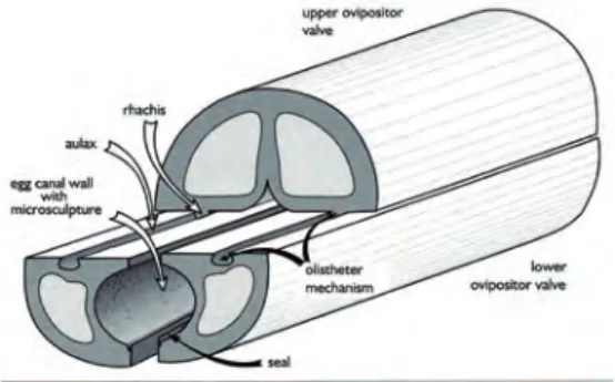
Large numbers of insects have ovipositors allowing them to lay their eggs. Some insects com-monly named “wood wasps" have ovipositors capable of drilling into wood to lay their eggs. Ovipositors also have numerous other functions like envenomation, defensive stinging or host location. For a more detailed description of ovipositors (evolutionary considerations, morphology, structures, oviposition strategies, etc.) refer to Quicke et al. (1999). Figure 1 is a middle region schematic of a typical ovipositor. The ovipositor has an upper or dorsal valve and two lower or ventral valves Rahman et al. (1998). Vincent and King Vincent & King (1995) described the morphology of two ovipositors: the short and rigid one of Sirex noctilio (10mm long and 0.26mm diameter) and the long and thin one of Megarhyssa nortoni nortoni (50mm long and 0.2mm diameter). They chose these two species because their ovipositors represent the large diversity of observed ovipositor morphologies of wood drilling wasps. They observed the ovipositors thanks to a Leica S440 scanning electron microscope. These observations revealed that the two ovipositors have different structures. Each ovipositor tip is covered with teeth. For both of these species the four first teeth at the tip of the ovipositor point proximally. In the case of M. n. nortoni the rest of the teeth also point proximally but decrease in size. For S. noctilio the following teeth progressively point distally. Differences in morphologies naturally induce differences in drilling mechanism.
Fig. 1. Schematic of the middle region of a typical ovipositor Rahman et al. (1998).
3.2 Drilling Mechanism
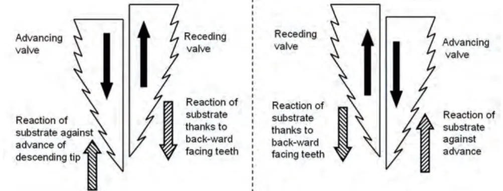
Vincent and King described the “drilling" mechanism of both of these species. The insect moves its two lower valves back and forth: when one valve is protruding the other is retracted and then the protruding valve is retracted and the retracted valve is deployed (see Figure 2). For both insects, the first teeth pointing proximally will engage in the cell wall of the wood cells and then break these cell walls in tension with the part of the ovipositor pulling upwards. The advantage of using such mechanism is that the available force is not limited by buckling considerations but only by the limit of insect muscular power. Before the upward stroke of the ovipositor can break the cell walls in tension, the downward stroke must allow the pushing part of the ovipositor to traverse the wood cell wall. To do so the required force is partially
generated by the overhead push of the insect on its ovipositor. This overhead push is limited by the critical buckling force of the ovipositor. To generate extra push the insect uses the tensile forces generated by its proximally facing teeth that are engaged in the wood cell walls. This also allows the receding valve to be in tension and to stabilize the ovipositor and reduces buckling risks. For M. n. nortoni, Vincent and King estimated the tension force to be ten times higher than the critical buckling load of the ovipositor. Thus the load that the insect can impose on the tip of the downward going valve of its ovipositor is principally generated by the resistance of the wood to the tensile forces of the upward moving valve (see Figure 2).
Fig. 2. Schematic of reciprocation movement and dual-reciprocating drill principle used by wood wasps.
3.3 Lessons learnt
When observing in detail the anatomy of the wood wasps’ ovipositor and the possible mech-anisms that could explain its capacity to drill into wood, two main “lessons" for drilling engi-neering can be learnt: “reaction generation" and “tension stabilisation". Reaction generation is the use of backward facing teeth to generate a reaction of the substrate in direction of drilling. The microstructures or the friction coefficient of the valve must be sufficient for the valve to mobilise the shearing resistance of the substrate and not slip on the surface of the substrate. Tension stabilisation is using the reaction of the substrate generated by the “reaction genera-tion" to create tension forces in the receding valve. The valve in tension is no longer subject to Euler buckling issues. Thanks to the ovipositor’s olistheter (sliding joint made of a T-shaped groove (aulax) on the lower valve and of a corresponding T-section ridge (rachis) on the up-per valve) the progressing valve which is in compression is linked to the valve in tension. If the critical buckling load of the compressed valve were to be exceeded, it would become un-stable and tend to buckle. But because it is linked to the other valve which is stabilized by the tension, the compressed valve can not deviate from its position. The valve in tension acts as a guide or support structure to the compressed valve. Thus the critical buckling load of the compressed valve can be exceeded without buckling issues. Many other observations of ovipositor morphology could lead to bio-mimetic applications (the ovipositors olistheter or the ovipositor steering mechanisms for instance).
is necessary before a fully functional 3D engineering model exists Menon et al. (n.d.). The wood-wasp inspired drill is the subject of this work.
3. The wood wasp ovipositor
3.1 Ovipositor morphology
Large numbers of insects have ovipositors allowing them to lay their eggs. Some insects com-monly named “wood wasps" have ovipositors capable of drilling into wood to lay their eggs. Ovipositors also have numerous other functions like envenomation, defensive stinging or host location. For a more detailed description of ovipositors (evolutionary considerations, morphology, structures, oviposition strategies, etc.) refer to Quicke et al. (1999). Figure 1 is a middle region schematic of a typical ovipositor. The ovipositor has an upper or dorsal valve and two lower or ventral valves Rahman et al. (1998). Vincent and King Vincent & King (1995) described the morphology of two ovipositors: the short and rigid one of Sirex noctilio (10mm long and 0.26mm diameter) and the long and thin one of Megarhyssa nortoni nortoni (50mm long and 0.2mm diameter). They chose these two species because their ovipositors represent the large diversity of observed ovipositor morphologies of wood drilling wasps. They observed the ovipositors thanks to a Leica S440 scanning electron microscope. These observations revealed that the two ovipositors have different structures. Each ovipositor tip is covered with teeth. For both of these species the four first teeth at the tip of the ovipositor point proximally. In the case of M. n. nortoni the rest of the teeth also point proximally but decrease in size. For S. noctilio the following teeth progressively point distally. Differences in morphologies naturally induce differences in drilling mechanism.
Fig. 1. Schematic of the middle region of a typical ovipositor Rahman et al. (1998).
3.2 Drilling Mechanism
Vincent and King described the “drilling" mechanism of both of these species. The insect moves its two lower valves back and forth: when one valve is protruding the other is retracted and then the protruding valve is retracted and the retracted valve is deployed (see Figure 2). For both insects, the first teeth pointing proximally will engage in the cell wall of the wood cells and then break these cell walls in tension with the part of the ovipositor pulling upwards. The advantage of using such mechanism is that the available force is not limited by buckling considerations but only by the limit of insect muscular power. Before the upward stroke of the ovipositor can break the cell walls in tension, the downward stroke must allow the pushing part of the ovipositor to traverse the wood cell wall. To do so the required force is partially
generated by the overhead push of the insect on its ovipositor. This overhead push is limited by the critical buckling force of the ovipositor. To generate extra push the insect uses the tensile forces generated by its proximally facing teeth that are engaged in the wood cell walls. This also allows the receding valve to be in tension and to stabilize the ovipositor and reduces buckling risks. For M. n. nortoni, Vincent and King estimated the tension force to be ten times higher than the critical buckling load of the ovipositor. Thus the load that the insect can impose on the tip of the downward going valve of its ovipositor is principally generated by the resistance of the wood to the tensile forces of the upward moving valve (see Figure 2).
Fig. 2. Schematic of reciprocation movement and dual-reciprocating drill principle used by wood wasps.
3.3 Lessons learnt
When observing in detail the anatomy of the wood wasps’ ovipositor and the possible mech-anisms that could explain its capacity to drill into wood, two main “lessons" for drilling engi-neering can be learnt: “reaction generation" and “tension stabilisation". Reaction generation is the use of backward facing teeth to generate a reaction of the substrate in direction of drilling. The microstructures or the friction coefficient of the valve must be sufficient for the valve to mobilise the shearing resistance of the substrate and not slip on the surface of the substrate. Tension stabilisation is using the reaction of the substrate generated by the “reaction genera-tion" to create tension forces in the receding valve. The valve in tension is no longer subject to Euler buckling issues. Thanks to the ovipositor’s olistheter (sliding joint made of a T-shaped groove (aulax) on the lower valve and of a corresponding T-section ridge (rachis) on the up-per valve) the progressing valve which is in compression is linked to the valve in tension. If the critical buckling load of the compressed valve were to be exceeded, it would become un-stable and tend to buckle. But because it is linked to the other valve which is stabilized by the tension, the compressed valve can not deviate from its position. The valve in tension acts as a guide or support structure to the compressed valve. Thus the critical buckling load of the compressed valve can be exceeded without buckling issues. Many other observations of ovipositor morphology could lead to bio-mimetic applications (the ovipositors olistheter or the ovipositor steering mechanisms for instance).
4. DRD technologies
4.1 Planetary Drill
The wood-wasp drilling mechanism proposed in Vincent & King (1995) fostered high hopes in the planetary drilling and sampling community. Apart from the general potential of biomimetic systems to be low-mass and efficient, the perspective of being able to generate the drilling forces between two valves with “no net external force required" (the receding valve generating the force required for the advancing valve) was of premium interest Gao et al. (2005). Indeed, as explained previously, space systems are constrained in mass and must operate in low gravity environments, thus the total over head force available for a drilling system is low. Classical rotary drilling techniques need high over-head forces and thus have limited performance in space applications Gao et al. (2005).
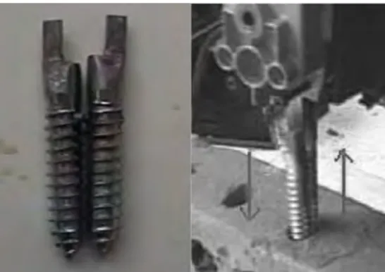
To asses the feasibility of the wood-wasp inspired drill a first experimental setup was built to measure the necessary cutting forces. The drill bits were manufactured in ABS plastic and the drilled substrate was polystyrene. The rack angle of the drill bit was varied as well as the cutting speed. Authors concluded thanks to these test that there is an optimal cutting speed to maximise drilling output power. The effects of the rack angle were also shown. Higher rake angles were shown to produce higher cutting forces. It was also shown that after increasing with cutting speed, the cutting force passes through a maximum and then decreases whatever the rack angle Gao et al. (2005). Further on a simple DRD mechanism with metal drill bits was built. A pin and crank mechanism that was positioned over the drill bits was used (see Figure 3).
Fig. 3. Picture of the planetary DRD first prototype (right) and of its drill bits (left) Gao, Ellery, Jaddou, Vincent & Eckersley (2007).
Three different drilled substrates were tested (condensed chalk, non fired clay and lime mor-tar) and drilled at 9 different power levels. This first prototype drilled faster in softer sub-strates (lower compressive strength) than in harder ones with the same input power. The fact that drilling speed generally grew with penetration depth was identified. This was explained by potential cracks that could have formed in the drilled substrate Gao, Ellery, Sweeting & Vincent (2007). Another potential explanation proposed here is that the deeper the drilled hole the more the backward facing teeth can engage in the drilled surface, thus allowing a higher WOB for penetrating valve. In Gao, Ellery, Sweeting & Vincent (2007) authors also proposed an empirical model allowing to predict the penetration speed vd of their DRD mechanism
based on input power P and substrate compressive strength as model inputs.
vd∝ k·P·√1
(1)
But above all the experimental work presented was the first implementation of DRD and proved the feasibility of DRD in soil and low strength rocks. Thanks to these first two studies, a light (<10kg) micro penetrator concept housing a DRD was proposed Gao, Ellery, Jaddou, Vincent & Eckersley (2007).
4.2 Brain Probe
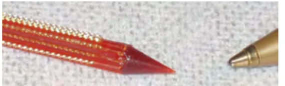
The wood wasp drilling mechanism described in Vincent & King (1995) has also fired new technological developments in neurosurgical probes (see Fig. 4). The possibility of being able to insert a fine probe under very low normal force into a brain could allow lowering the damage done to a brain during minimal invasive surgery Parittotokkaporn et al. (2009). The flexibility and the possibility of being able to steer a flexible neurosurgical probe like an ovipositor is steered would enable surgeons to avoid key zones of the brain when operating. For the moment this is limited by the rigid probes used Frasson, Parittotokkaporn, Schneider, Davies, Vincent, Huq, Degenaar & Baena (2008). However it is important to note that the main function of the ovipositor is to remove wood whereas the neurosurgical probe should displace tissue.
Fig. 4. Picture of the brain probe prototype (left) and pen as size reference (right) Frasson, Parittotokkaporn, Davies & Rodriguez y Baena (2008).
Inspired by the texture of the ovipositor of Sirex Noctilio, surfaces having different tribolog-ical properties depending on the direction in which they are moved were manufactured. To emulate the surface of an ovipositor, fin and tooth like microstructures with high-aspect ratios were manufactured thanks to advanced microelectronic mechanical systems (MEMS) fabrica-tion technique. A large range of micro-structure size were manufactured (ranging from 10µm to 500µm). For more details on manufacturing and related issues refer to Schneider et al. (2008; 2009).
A first series of tests were conducted thanks to the manufactured micro-structures. The goal was to determine whether or not the reciprocating motion of the microstructures was suffi-cient to induce the displacement of a specimen. The specimens tested ranged from in-organic materials to organic and also biological ones. The microstructures were reciprocated on the surface of each tested specimen. A specific air bearing was designed to lower the friction the specimen was subject to. It was showed that most soft organic tissues and most inorganic ma-terials did not allow the micro structures to have sufficient grip on the specimen for it to move significantly. A good correlation between the microtexture size and the slip on the specimen was found. Five different microstructure/specimen interaction mechanisms were proposed. The damage created by the microstructures during the reciprocation motion was also inves-tigated. This first work proved the feasibility of soft tissue traversal thanks to anisotropic
4. DRD technologies
4.1 Planetary Drill
The wood-wasp drilling mechanism proposed in Vincent & King (1995) fostered high hopes in the planetary drilling and sampling community. Apart from the general potential of biomimetic systems to be low-mass and efficient, the perspective of being able to generate the drilling forces between two valves with “no net external force required" (the receding valve generating the force required for the advancing valve) was of premium interest Gao et al. (2005). Indeed, as explained previously, space systems are constrained in mass and must operate in low gravity environments, thus the total over head force available for a drilling system is low. Classical rotary drilling techniques need high over-head forces and thus have limited performance in space applications Gao et al. (2005).
To asses the feasibility of the wood-wasp inspired drill a first experimental setup was built to measure the necessary cutting forces. The drill bits were manufactured in ABS plastic and the drilled substrate was polystyrene. The rack angle of the drill bit was varied as well as the cutting speed. Authors concluded thanks to these test that there is an optimal cutting speed to maximise drilling output power. The effects of the rack angle were also shown. Higher rake angles were shown to produce higher cutting forces. It was also shown that after increasing with cutting speed, the cutting force passes through a maximum and then decreases whatever the rack angle Gao et al. (2005). Further on a simple DRD mechanism with metal drill bits was built. A pin and crank mechanism that was positioned over the drill bits was used (see Figure 3).
Fig. 3. Picture of the planetary DRD first prototype (right) and of its drill bits (left) Gao, Ellery, Jaddou, Vincent & Eckersley (2007).
Three different drilled substrates were tested (condensed chalk, non fired clay and lime mor-tar) and drilled at 9 different power levels. This first prototype drilled faster in softer sub-strates (lower compressive strength) than in harder ones with the same input power. The fact that drilling speed generally grew with penetration depth was identified. This was explained by potential cracks that could have formed in the drilled substrate Gao, Ellery, Sweeting & Vincent (2007). Another potential explanation proposed here is that the deeper the drilled hole the more the backward facing teeth can engage in the drilled surface, thus allowing a higher WOB for penetrating valve. In Gao, Ellery, Sweeting & Vincent (2007) authors also proposed an empirical model allowing to predict the penetration speed vd of their DRD mechanism
based on input power P and substrate compressive strength as model inputs.
vd∝ k·P·√1
(1)
But above all the experimental work presented was the first implementation of DRD and proved the feasibility of DRD in soil and low strength rocks. Thanks to these first two studies, a light (<10kg) micro penetrator concept housing a DRD was proposed Gao, Ellery, Jaddou, Vincent & Eckersley (2007).
4.2 Brain Probe
The wood wasp drilling mechanism described in Vincent & King (1995) has also fired new technological developments in neurosurgical probes (see Fig. 4). The possibility of being able to insert a fine probe under very low normal force into a brain could allow lowering the damage done to a brain during minimal invasive surgery Parittotokkaporn et al. (2009). The flexibility and the possibility of being able to steer a flexible neurosurgical probe like an ovipositor is steered would enable surgeons to avoid key zones of the brain when operating. For the moment this is limited by the rigid probes used Frasson, Parittotokkaporn, Schneider, Davies, Vincent, Huq, Degenaar & Baena (2008). However it is important to note that the main function of the ovipositor is to remove wood whereas the neurosurgical probe should displace tissue.
Fig. 4. Picture of the brain probe prototype (left) and pen as size reference (right) Frasson, Parittotokkaporn, Davies & Rodriguez y Baena (2008).
Inspired by the texture of the ovipositor of Sirex Noctilio, surfaces having different tribolog-ical properties depending on the direction in which they are moved were manufactured. To emulate the surface of an ovipositor, fin and tooth like microstructures with high-aspect ratios were manufactured thanks to advanced microelectronic mechanical systems (MEMS) fabrica-tion technique. A large range of micro-structure size were manufactured (ranging from 10µm to 500µm). For more details on manufacturing and related issues refer to Schneider et al. (2008; 2009).
A first series of tests were conducted thanks to the manufactured micro-structures. The goal was to determine whether or not the reciprocating motion of the microstructures was suffi-cient to induce the displacement of a specimen. The specimens tested ranged from in-organic materials to organic and also biological ones. The microstructures were reciprocated on the surface of each tested specimen. A specific air bearing was designed to lower the friction the specimen was subject to. It was showed that most soft organic tissues and most inorganic ma-terials did not allow the micro structures to have sufficient grip on the specimen for it to move significantly. A good correlation between the microtexture size and the slip on the specimen was found. Five different microstructure/specimen interaction mechanisms were proposed. The damage created by the microstructures during the reciprocation motion was also inves-tigated. This first work proved the feasibility of soft tissue traversal thanks to anisotropic
frictional properties and reciprocating motions with minimal tissue damage Parittotokkaporn et al. (2009).
The microstructures were then mounted onto a neurosurgical probe. The dynamic properties of the probes in a bi-directional axial displacement test done in brain tissues were explored. The forces necessary for their surgical probe to progress and the forces generated during the retraction of the probe were recorded. Since these two forces are of the same order of mag-nitude they have concluded that a brain probe using dual-reciprocating-drilling is feasible. Such a surgical tool would thus take benefit of the anisotropic tribological properties of its surface to progress thanks to reciprocating motion. It was even showed that the presence of the microstructures on the probe reduces the necessary amount of force to insert the probe in the brain tissues (when compared to a smooth probe)Frasson, Parittotokkaporn, Davies & Rodriguez y Baena (2008). The future work planned on this development include: the under-standing of the tissue/probe interaction and the exploration of the effects of the normal force, of tissue properties and of reciprocating speed on soft tissue traversal.
4.3 Dual-Reciprocating-Drilling
As shown above, the wood-wasp drilling mechanism has inspired different technological de-velopments. Here and in further publications the wood-wasp inspired drilling mechanism will be referred to as dual-reciprocating drilling. Indeed the drilling mechanism is based on the reciprocation motion of two tools or valves. Any drilling mechanism which disrupts or progresses into the drilled substrate thanks to the reciprocation of two tools in opposition one to another will be referred to as dual-reciprocating drilling (DRD). In DRD, the two recipro-cated tools will be referred to as valves like in the wood-wasp morphology or drill bits. 4.4 Study Rationales
In Gao, Ellery, Sweeting & Vincent (2007), Gao et. al. highlighted some interesting research to be done on their DRD: optimize the geometry of drill bit, experiment on a wide variety of substrates, work on sample extraction method and build a prototype. In Frasson, Parit-totokkaporn, Davies & Rodriguez y Baena (2008), Frasson et. al. have also insisted on the numerous studies needed before a fully functional brain probe can be proposed to neuro-surgeons. Even the observations of the morphology of ovipositors still have much room for progress: “Almost nothing is known about the mechanics of substrate penetration and the interactions between the ovipositor valves and the substrate. No measurements of the rate or extents of ovipositor valve movements are available [...]." Quicke et al. (1999). Before an operational and space-qualified DRD can be proposed to solar system exploration missions it is key that more knowledge be collected. Two main questions need answering
4.4.1 What fundamental mechanism does DRD use to penetrate planetary soils?
Vincent and King proposed a basic drilling mechanism for the wood wasp’s ovipositor. Though there is still room for more in depth understanding, it is very satisfying. However it is very unlikely that the mechanism they have described is applicable to a planetary DRD advancing in lunar regolith. Indeed wood is made of fibres but regolith is not. It is thought that the teeth of the wood wasp ovipositor have been optimised (through natural selection) to the size of wood cell walls. Further more, it is unclear whether or not a planetary DRD would use the same basic mechanism of progression in a granular material and in a soft rock formation. However understanding the fundamental drilling mechanism is key. This would allow engineers to optimize their designs.
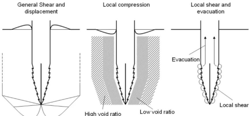
For the moment three possible basic drilling mechanisms have been identified: displacement, compression and local shear/evacuation (see Fig. 5). In order to penetrate the substrate a mole, like the Beagle 2 Pluto mole, will displace the substrate around it. The substrate directly in front of the tip will be pushed down; the substrate further away will be pushed to the side and up. Upheaval of the substrate at the surface will be observed around the DRD. It is also likely that the displacement of the substrate will be accompanied by compression of the substrate. In some cases (high initial void ratio or low relative density of the substrate) compression will dominate. The compression of the substrate in the local vicinity of the drill will be sufficient to create enough room for the drill to progress. In such cases the substrate directly around the drill will be compressed and the substrate further away from the drill will not be affected (no displacement nor compression). A dip in the ground level around the DRD will be observed. The final mechanism is local shear and evacuation. It is possible to locally shear and displace the substrate and evacuate it. This method is the most similar to classical rotary drilling. Since this mechanism allows very localised action, it intuitively has the best low-energy potential. Whether these are applicable to a planetary DRD in planetary regolith is the first major contribution envisaged for this work. It is possible that none of the three mechanisms proposed allow a correct interpretation of our future observations and that a new mechanisms will have to be proposed.
Fig. 5. Illustration of the three proposed basic drilling processes.
A very closely linked issue is the identification of the progression mechanism. Indeed it is unclear whether the force generated by the backward facing teeth of the receding valve is sufficient to make the entire drill progress. This is unclear even in the biological system. Little detail is given on the progression of the entire ovipositor and the role of the third valve. 4.4.2 Which parameters influence DRD performance?
For the moment only substrate compressive strength and input power have been explored and linked to drilling speed (see Equation 1). However a large number of parameters could play a role in DRD performance and force and power requirements. Before optimised planetary DRD designs can be proposed it is necessary that the key parameters driving DRD be identified. Parameters potentially playing a role in DRD have been identified and split into 3 categories: geometry of the drill head, operational parameters and substrate properties.
frictional properties and reciprocating motions with minimal tissue damage Parittotokkaporn et al. (2009).
The microstructures were then mounted onto a neurosurgical probe. The dynamic properties of the probes in a bi-directional axial displacement test done in brain tissues were explored. The forces necessary for their surgical probe to progress and the forces generated during the retraction of the probe were recorded. Since these two forces are of the same order of mag-nitude they have concluded that a brain probe using dual-reciprocating-drilling is feasible. Such a surgical tool would thus take benefit of the anisotropic tribological properties of its surface to progress thanks to reciprocating motion. It was even showed that the presence of the microstructures on the probe reduces the necessary amount of force to insert the probe in the brain tissues (when compared to a smooth probe)Frasson, Parittotokkaporn, Davies & Rodriguez y Baena (2008). The future work planned on this development include: the under-standing of the tissue/probe interaction and the exploration of the effects of the normal force, of tissue properties and of reciprocating speed on soft tissue traversal.
4.3 Dual-Reciprocating-Drilling
As shown above, the wood-wasp drilling mechanism has inspired different technological de-velopments. Here and in further publications the wood-wasp inspired drilling mechanism will be referred to as dual-reciprocating drilling. Indeed the drilling mechanism is based on the reciprocation motion of two tools or valves. Any drilling mechanism which disrupts or progresses into the drilled substrate thanks to the reciprocation of two tools in opposition one to another will be referred to as dual-reciprocating drilling (DRD). In DRD, the two recipro-cated tools will be referred to as valves like in the wood-wasp morphology or drill bits. 4.4 Study Rationales
In Gao, Ellery, Sweeting & Vincent (2007), Gao et. al. highlighted some interesting research to be done on their DRD: optimize the geometry of drill bit, experiment on a wide variety of substrates, work on sample extraction method and build a prototype. In Frasson, Parit-totokkaporn, Davies & Rodriguez y Baena (2008), Frasson et. al. have also insisted on the numerous studies needed before a fully functional brain probe can be proposed to neuro-surgeons. Even the observations of the morphology of ovipositors still have much room for progress: “Almost nothing is known about the mechanics of substrate penetration and the interactions between the ovipositor valves and the substrate. No measurements of the rate or extents of ovipositor valve movements are available [...]." Quicke et al. (1999). Before an operational and space-qualified DRD can be proposed to solar system exploration missions it is key that more knowledge be collected. Two main questions need answering
4.4.1 What fundamental mechanism does DRD use to penetrate planetary soils?
Vincent and King proposed a basic drilling mechanism for the wood wasp’s ovipositor. Though there is still room for more in depth understanding, it is very satisfying. However it is very unlikely that the mechanism they have described is applicable to a planetary DRD advancing in lunar regolith. Indeed wood is made of fibres but regolith is not. It is thought that the teeth of the wood wasp ovipositor have been optimised (through natural selection) to the size of wood cell walls. Further more, it is unclear whether or not a planetary DRD would use the same basic mechanism of progression in a granular material and in a soft rock formation. However understanding the fundamental drilling mechanism is key. This would allow engineers to optimize their designs.
For the moment three possible basic drilling mechanisms have been identified: displacement, compression and local shear/evacuation (see Fig. 5). In order to penetrate the substrate a mole, like the Beagle 2 Pluto mole, will displace the substrate around it. The substrate directly in front of the tip will be pushed down; the substrate further away will be pushed to the side and up. Upheaval of the substrate at the surface will be observed around the DRD. It is also likely that the displacement of the substrate will be accompanied by compression of the substrate. In some cases (high initial void ratio or low relative density of the substrate) compression will dominate. The compression of the substrate in the local vicinity of the drill will be sufficient to create enough room for the drill to progress. In such cases the substrate directly around the drill will be compressed and the substrate further away from the drill will not be affected (no displacement nor compression). A dip in the ground level around the DRD will be observed. The final mechanism is local shear and evacuation. It is possible to locally shear and displace the substrate and evacuate it. This method is the most similar to classical rotary drilling. Since this mechanism allows very localised action, it intuitively has the best low-energy potential. Whether these are applicable to a planetary DRD in planetary regolith is the first major contribution envisaged for this work. It is possible that none of the three mechanisms proposed allow a correct interpretation of our future observations and that a new mechanisms will have to be proposed.
Fig. 5. Illustration of the three proposed basic drilling processes.
A very closely linked issue is the identification of the progression mechanism. Indeed it is unclear whether the force generated by the backward facing teeth of the receding valve is sufficient to make the entire drill progress. This is unclear even in the biological system. Little detail is given on the progression of the entire ovipositor and the role of the third valve. 4.4.2 Which parameters influence DRD performance?
For the moment only substrate compressive strength and input power have been explored and linked to drilling speed (see Equation 1). However a large number of parameters could play a role in DRD performance and force and power requirements. Before optimised planetary DRD designs can be proposed it is necessary that the key parameters driving DRD be identified. Parameters potentially playing a role in DRD have been identified and split into 3 categories: geometry of the drill head, operational parameters and substrate properties.
4.4.2.1 Geometry of drill head
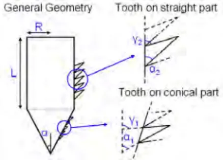
The wood wasp ovipositor morphology being highly complex, it is impossible to mimic it fully. A simplified geometry has been adopted. Each DRD valve will be a half cone on top of a half cylinder. Such a general form is defined by three parameters: cone apex angle α, cylinder radius R, and cylinder length L. Each part of the DRD valve (cone and cylinder) will have specific tooth geometry. To define each tooth we need to know: two angles (respectively α1,
γ1 and α2, γ2) and the number of teeth on each part (respectively N1 and N2). The geometry
of the DRD valves is thus fully defined by nine geometrical parameters (see Figure 6).
Fig. 6. Schematic of drill head geometry.
4.4.2.2 Operational parameters
How the valves are displaced must also be defined. The reciprocation motion is defined by its amplitude (δ) and its frequency ( f ). These two parameters are linked to others like input voltage, input current, input power and drilling speed. The depth d of the DRD valves and the over-head force or mass available to push on the drill are also very important operational parameters.
4.4.2.3 Substrate parameters
DRD technology is very novel and its full potential is not yet understood. It is thus important that it be tested in a wide variety of substrates: high void ratio sands, low void ratio regolith simulants and low unconfined strength rocks like the ones used in Gao, Ellery, Sweeting & Vincent (2007). Defining a set of parameters to describe the mechanical properties of rocks and granular materials alike is not feasible. For granular materials, angle of internal friction, cohesion, particle size distribution, angularity, density and void ratio can be considered. For soft cohesive formations unconfined compressive strength, elastic modulus and shear modu-lus can be considered.
5. Experimental Setup
5.1 A new DRD test bench 5.1.1 Design constraints
To answer the two main questions exposed in subsection 4.4, a new DRD test bench was de-signed. This new test bench presents added functionality compared to the first planetary DRD prototype. Indeed it allows the exploration of a wider range of parameters: variation of drill valve geometry, reciprocation movement amplitude and frequency. Apart from reciprocation
movement frequency, this was not feasible in the first planetary DRD prototype. But above all, this new DRD test bench was designed to allow the control of the over-head weight or force acting on the DRD valves. Indeed the added-value foreseen in a planetary DRD is its ability to drill with little or no over-head force requirements. A strict control of the over-head force on the DRD valves was not implemented on the first planetary DRD prototype. The new DRD test bench has a counter-mass and pulley system to control the vertical force acting upon the DRD. However, because of the numerous new functions, the mass of the test bench is significantly higher than the mass of previous setup.
5.1.2 Test bench description
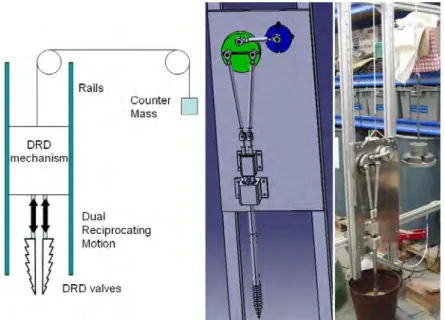
A schematic, CAD-view and a picture of the new DRD test bench are presented Figure 7. The main elements of the test bench are the DRD mechanism (made of a motor, a movement trans-formation mechanism and the DRD valves) fixed on an aluminium plate, two rails guiding the aluminium plate (vertical translation), a counter mass system with two pulleys, and the data acquisition and control chains.
Fig. 7. Schematic and picture of DRD test bench.
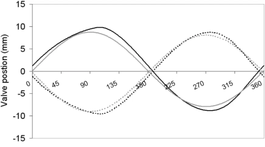
The DRD mechanism is made of a continuous current motor, a movement transformation mechanism and the DRD valves. To transform the rotation of the motor into a dual recipro-cation motion, a three rod, double pin and crank mechanism was manufactured. In order to allow modification of the amplitude without deeply transforming the reciprocation cycle and its symmetry, it is possible to modify the lengths as well as the fixation points of the roods. Figure 8 illustrates some possible valve movements that the DRD test bench can produce (grey lines) and some valve movements it would have produced if the length of the rods had not been modifiable (black lines).
4.4.2.1 Geometry of drill head
The wood wasp ovipositor morphology being highly complex, it is impossible to mimic it fully. A simplified geometry has been adopted. Each DRD valve will be a half cone on top of a half cylinder. Such a general form is defined by three parameters: cone apex angle α, cylinder radius R, and cylinder length L. Each part of the DRD valve (cone and cylinder) will have specific tooth geometry. To define each tooth we need to know: two angles (respectively α1,
γ1 and α2, γ2) and the number of teeth on each part (respectively N1 and N2). The geometry
of the DRD valves is thus fully defined by nine geometrical parameters (see Figure 6).
Fig. 6. Schematic of drill head geometry.
4.4.2.2 Operational parameters
How the valves are displaced must also be defined. The reciprocation motion is defined by its amplitude (δ) and its frequency ( f ). These two parameters are linked to others like input voltage, input current, input power and drilling speed. The depth d of the DRD valves and the over-head force or mass available to push on the drill are also very important operational parameters.
4.4.2.3 Substrate parameters
DRD technology is very novel and its full potential is not yet understood. It is thus important that it be tested in a wide variety of substrates: high void ratio sands, low void ratio regolith simulants and low unconfined strength rocks like the ones used in Gao, Ellery, Sweeting & Vincent (2007). Defining a set of parameters to describe the mechanical properties of rocks and granular materials alike is not feasible. For granular materials, angle of internal friction, cohesion, particle size distribution, angularity, density and void ratio can be considered. For soft cohesive formations unconfined compressive strength, elastic modulus and shear modu-lus can be considered.
5. Experimental Setup
5.1 A new DRD test bench 5.1.1 Design constraints
To answer the two main questions exposed in subsection 4.4, a new DRD test bench was de-signed. This new test bench presents added functionality compared to the first planetary DRD prototype. Indeed it allows the exploration of a wider range of parameters: variation of drill valve geometry, reciprocation movement amplitude and frequency. Apart from reciprocation
movement frequency, this was not feasible in the first planetary DRD prototype. But above all, this new DRD test bench was designed to allow the control of the over-head weight or force acting on the DRD valves. Indeed the added-value foreseen in a planetary DRD is its ability to drill with little or no over-head force requirements. A strict control of the over-head force on the DRD valves was not implemented on the first planetary DRD prototype. The new DRD test bench has a counter-mass and pulley system to control the vertical force acting upon the DRD. However, because of the numerous new functions, the mass of the test bench is significantly higher than the mass of previous setup.
5.1.2 Test bench description
A schematic, CAD-view and a picture of the new DRD test bench are presented Figure 7. The main elements of the test bench are the DRD mechanism (made of a motor, a movement trans-formation mechanism and the DRD valves) fixed on an aluminium plate, two rails guiding the aluminium plate (vertical translation), a counter mass system with two pulleys, and the data acquisition and control chains.
Fig. 7. Schematic and picture of DRD test bench.
The DRD mechanism is made of a continuous current motor, a movement transformation mechanism and the DRD valves. To transform the rotation of the motor into a dual recipro-cation motion, a three rod, double pin and crank mechanism was manufactured. In order to allow modification of the amplitude without deeply transforming the reciprocation cycle and its symmetry, it is possible to modify the lengths as well as the fixation points of the roods. Figure 8 illustrates some possible valve movements that the DRD test bench can produce (grey lines) and some valve movements it would have produced if the length of the rods had not been modifiable (black lines).
Fig. 8. Possible valve movements of the DRD test bench versus motor angle. Grey lines rep-resent valve movements obtained thanks to the modifiable rod length; black lines reprep-resent movement obtained if rod had a set length. Dotted lines are left valve, full lines are right valve.
The counter-mass is setup with two pulleys. Interpretation of the role of the counter-mass must be done with caution. Indeed the counter-mass does not allow to mimic low gravity. If the global equilibrium of the plate supporting the DRD mechanism is considered, it can be seen that the vertical force on the valves does depend on the value of the counter-mass, but the maximum difference between the two valves does not. It is the strength of the rails that determine this value. If the DRD were housed in a rover or robot on the surface of the Moon or Mars, the maximum allowable force difference between the valves would be determined in part by gravity (and also by the carrier’s geometrical setup). Another element that the counter-mass does not allow to control is the role of gravity on the drilled substrate. Experimental studies have been lead in partial gravity conditions to show the influence of gravity on bearing capacity of soils and have showed that gravity must be taken into account Bui et al. (2009). The electric motor frequency is controlled by varying input voltage. The input current and input voltage are monitored by TTI Multimeters and recorded automatically by a data acqui-sition desk top computer (at 0.5 Hz). The depth of the drill is recorded thanks to an image capture system. Its data acquisition frequency is also set to 0.5 Hz. For further details refer to Gouache et al. (2009b).
5.2 Substrates
As described by Neil Armstrong (Tranquillity Base, Apollo 11, July 20, 1969), the surface of the Moon appears to be “very, very fine-grained, as you get close to it, it’s almost like a pow-der; down there, it’s very fine [...] I can see the footprints of my boots and the treads in the fine sandy particles." . The samples brought back to Earth by the Luna and Apollo missions have widely been studied Heiken et al. (1991). The Moon is covered by regolith, a granular material. The surface of Mars is also covered by regolith though its origin (most probably weathering and communition through impacts and wind more than chemical, biological and
water action) is believed to be different than Lunar regolith’s origin (micrometeorites and me-teorite impacts) Seiferlin et al. (2008). Since no large quantities of Lunar or Martian regolith are available on Earth, it is mandatory to rely on simulants. For mechanical testing (drilling, traficability, etc.) the mechanical properties of the simulant are more important than its chem-ical composition. Sands have already been used to simulate regolith. For instance the Beagle 2 mole was tested in sand Richter et al. (2001). Two sands have been identified and charac-terised as suitable Mars simulants at the Surrey Space Centre: SSC-1 and SSC-2. SSC-1 is a coarse-silty quartz sand and SSC-2 is a fine garnet sand. The mechanical properties of these two simulants and their particle distributions are given in Scott & Saaj (2009).
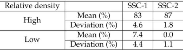
It has been noticed that the void ratio or relative density of a sand can influence (or even dominate) the behaviour of a structure interacting with it: traficability of rovers Brunskill & Vaios (2009); Scott & Saaj (2009) or penetration forces El Shafie et al. (2009) for instance. Thus, two substrate preparation methods were designed: one to obtain a low relative density substrate and the other one to obtain a high relative density substrate. Efforts have been focused on proposing a robust method able to reproduce the same relative density for a given substrate. The low relative density substrate is obtained by pouring the substrate into its container. The height of pouring and flow rate can have an incidence on the obtained density. It was observed that for heights above 40cm, there is little influence on final density. Thus all pouring were done from at least 50 cm high. The high relative density substrate is obtained by pouring the substrate into its container that is positioned on a vibrating table. Here the height of pouring has no influence on final density. Each of these methods was tested five times on both SSC-1 and SSC-2 (a total of 20 runs). The results of these tests are shown in table 1. The levels of relative density obtained are sufficiently spaced out (over 80% and under 10%) and low levels of deviation are observed (less than 5%). On the poured technique two runs (one with SSC-1 and one with SSC-2) gave anomalous results and were disregarded.
Relative density SSC-1 SSC-2
High Deviation (%)Mean (%) 4.683 1.887 Low Deviation (%)Mean (%) 7.44.4 0.01.1
Table 1. Mean relative density and relative density deviation of SSC-1 and SSC-2 with high and low relative density preparation methods.
5.3 Design of experiment
The wide range of parameters potentially influencing DRD performance and the novelty of the technique have pushed authors to use design of experiment techniques. Indeed they al-low to asses the influence of a large number of parameters by screening experiments while minimising the number of experiments to be done. A very complete presentation of such techniques is given in Montgomery (2009).
5.3.1 Inputs and outputs
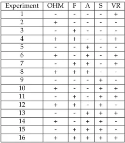
Here we have chosen to keep the same drill head geometry. The studied inputs with their low and high levels are:
Fig. 8. Possible valve movements of the DRD test bench versus motor angle. Grey lines rep-resent valve movements obtained thanks to the modifiable rod length; black lines reprep-resent movement obtained if rod had a set length. Dotted lines are left valve, full lines are right valve.
The counter-mass is setup with two pulleys. Interpretation of the role of the counter-mass must be done with caution. Indeed the counter-mass does not allow to mimic low gravity. If the global equilibrium of the plate supporting the DRD mechanism is considered, it can be seen that the vertical force on the valves does depend on the value of the counter-mass, but the maximum difference between the two valves does not. It is the strength of the rails that determine this value. If the DRD were housed in a rover or robot on the surface of the Moon or Mars, the maximum allowable force difference between the valves would be determined in part by gravity (and also by the carrier’s geometrical setup). Another element that the counter-mass does not allow to control is the role of gravity on the drilled substrate. Experimental studies have been lead in partial gravity conditions to show the influence of gravity on bearing capacity of soils and have showed that gravity must be taken into account Bui et al. (2009). The electric motor frequency is controlled by varying input voltage. The input current and input voltage are monitored by TTI Multimeters and recorded automatically by a data acqui-sition desk top computer (at 0.5 Hz). The depth of the drill is recorded thanks to an image capture system. Its data acquisition frequency is also set to 0.5 Hz. For further details refer to Gouache et al. (2009b).
5.2 Substrates
As described by Neil Armstrong (Tranquillity Base, Apollo 11, July 20, 1969), the surface of the Moon appears to be “very, very fine-grained, as you get close to it, it’s almost like a pow-der; down there, it’s very fine [...] I can see the footprints of my boots and the treads in the fine sandy particles." . The samples brought back to Earth by the Luna and Apollo missions have widely been studied Heiken et al. (1991). The Moon is covered by regolith, a granular material. The surface of Mars is also covered by regolith though its origin (most probably weathering and communition through impacts and wind more than chemical, biological and
water action) is believed to be different than Lunar regolith’s origin (micrometeorites and me-teorite impacts) Seiferlin et al. (2008). Since no large quantities of Lunar or Martian regolith are available on Earth, it is mandatory to rely on simulants. For mechanical testing (drilling, traficability, etc.) the mechanical properties of the simulant are more important than its chem-ical composition. Sands have already been used to simulate regolith. For instance the Beagle 2 mole was tested in sand Richter et al. (2001). Two sands have been identified and charac-terised as suitable Mars simulants at the Surrey Space Centre: SSC-1 and SSC-2. SSC-1 is a coarse-silty quartz sand and SSC-2 is a fine garnet sand. The mechanical properties of these two simulants and their particle distributions are given in Scott & Saaj (2009).
It has been noticed that the void ratio or relative density of a sand can influence (or even dominate) the behaviour of a structure interacting with it: traficability of rovers Brunskill & Vaios (2009); Scott & Saaj (2009) or penetration forces El Shafie et al. (2009) for instance. Thus, two substrate preparation methods were designed: one to obtain a low relative density substrate and the other one to obtain a high relative density substrate. Efforts have been focused on proposing a robust method able to reproduce the same relative density for a given substrate. The low relative density substrate is obtained by pouring the substrate into its container. The height of pouring and flow rate can have an incidence on the obtained density. It was observed that for heights above 40cm, there is little influence on final density. Thus all pouring were done from at least 50 cm high. The high relative density substrate is obtained by pouring the substrate into its container that is positioned on a vibrating table. Here the height of pouring has no influence on final density. Each of these methods was tested five times on both SSC-1 and SSC-2 (a total of 20 runs). The results of these tests are shown in table 1. The levels of relative density obtained are sufficiently spaced out (over 80% and under 10%) and low levels of deviation are observed (less than 5%). On the poured technique two runs (one with SSC-1 and one with SSC-2) gave anomalous results and were disregarded.
Relative density SSC-1 SSC-2
High Deviation (%)Mean (%) 4.683 1.887 Low Deviation (%)Mean (%) 7.44.4 0.01.1
Table 1. Mean relative density and relative density deviation of SSC-1 and SSC-2 with high and low relative density preparation methods.
5.3 Design of experiment
The wide range of parameters potentially influencing DRD performance and the novelty of the technique have pushed authors to use design of experiment techniques. Indeed they al-low to asses the influence of a large number of parameters by screening experiments while minimising the number of experiments to be done. A very complete presentation of such techniques is given in Montgomery (2009).
5.3.1 Inputs and outputs
Here we have chosen to keep the same drill head geometry. The studied inputs with their low and high levels are: